Audio opamps will probably have more output inductance than a discrete shunt reg because they are designed for good performance in the audio region.
The question is, what is not already as good as it can be in the current design?
The question is, what is not already as good as it can be in the current design?
It's just a proposal, op amps can be swapped with more capable ones. The idea is to buffer the reference.
An opamp has around +-25mA max output whereas the TL431 is limited to its bias current, so you would have 10 times more speed, assuming it could be stable. But, I don't think speed is a problem this design currently has. It could be useful to use an opamp to filter out more noise from the reference, if the noise in the reference is shown to be a problem. However I would look for simpler solutions first.
The idea is to enhance TL431 performance. 470R/100uF are there for noise filtering & soft start. Opamp buffers goes to 500 mA and more as this PSU is intended for preamp.
But if your opamp is pushing 500mA into the cap, this current is also going into the rails, causing the problem it's supposed to solve. And if you put the opamp on a separate supply, it's PSRR will dominate the output. And then, are there any good opamps that work on 3.3V with inputs close to the rails? This is getting very complex.
Well, I got my hands on a Subbu +5V power supply (the one that goes with the Subbu DAC), so I tested it, too.
File #1 : Noise and Ripple = 50 µVpp (10µV RMS) (1Hz-100kHz) with 100R load.
Very good result for a mains powered supply !
No high frequency garbage. Looks good.
A x1000 preamp is used, so the mV scale on the scope is actually µV.
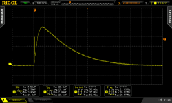
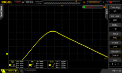
File #2, #3 : Transient response 15mA to 45mA
The 723 is of course a bit slow, but the response is well damped.
This isn't really a problem since this supply is designed to power a board through wires, and the inductance of these wires will slow down the transient response anyway. A very fast regulator has to be close to the load.
The output capacitor is a very small electrolytic. This is good, since the capacitors should not be on the power supply board, but close to the load. For example, putting ceramic caps at the output on the power supply board would be a mistake... they would be in the wrong place.
Next 2 tests are done on a board which is powered by this supply. The board has a local decoupling capacitor (470µF Nichicon LF).
File #4 : Transient response 15mA to 45mA
It looks much better now, with local decoupling.
Last file : Output impedance.
30 mOhm at DC (including the wires). There is no sign of resonance or instability. Distortion is low, which means the output impedance is quite linear.
To suppress the impedance bump, a higher value local decoupling capacitor could be used.
If the purpose is to feed local LDOs like in the Subbu DAC, no problem.
Conclusion : Nice little power supply, very low noise and ripple, works well. It is well suited to its intended use.
File #1 : Noise and Ripple = 50 µVpp (10µV RMS) (1Hz-100kHz) with 100R load.
Very good result for a mains powered supply !
No high frequency garbage. Looks good.
A x1000 preamp is used, so the mV scale on the scope is actually µV.
File #2, #3 : Transient response 15mA to 45mA
The 723 is of course a bit slow, but the response is well damped.
This isn't really a problem since this supply is designed to power a board through wires, and the inductance of these wires will slow down the transient response anyway. A very fast regulator has to be close to the load.
The output capacitor is a very small electrolytic. This is good, since the capacitors should not be on the power supply board, but close to the load. For example, putting ceramic caps at the output on the power supply board would be a mistake... they would be in the wrong place.
Next 2 tests are done on a board which is powered by this supply. The board has a local decoupling capacitor (470µF Nichicon LF).
File #4 : Transient response 15mA to 45mA
It looks much better now, with local decoupling.
Last file : Output impedance.
30 mOhm at DC (including the wires). There is no sign of resonance or instability. Distortion is low, which means the output impedance is quite linear.
To suppress the impedance bump, a higher value local decoupling capacitor could be used.
If the purpose is to feed local LDOs like in the Subbu DAC, no problem.
Conclusion : Nice little power supply, very low noise and ripple, works well. It is well suited to its intended use.
Attachments


Last edited:
Two more tests, using only the power supply, not the test-board with 470µF capacitor :
EMI Test :
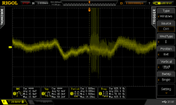
Of course, all is not perfect, so here comes the dreaded cellphone test. I put my cellphone on the mains power cable, make a call, and look at the power supply output on the scope. I try to position the cellphone so it gives maximum interference.
I could get 10mV pk RF detection at the output.
Eco-light Test :
I plug the supply on the same power bar as a lamp with an eco-friendly bulb (ie, big interference source), and switch the lamp on and off. The scope's trigger is set to catch the event.
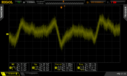
Here, the x1000 preamp is used. Even though it looks nasty on the scope, the interference burst is only about 100µV of HF. The local capacitors on the DAC board will neutralize it.
The trace looks noisier once the lamp is switched on, so I ran a test with the power supply unplugged. The preamp runs on batteries, so the lamp switch-on noise burst is completely absent from the output, however the lamp's electromagnetic emissions are picked up by the cabling and the PCB. So the noisier trace after switching on the lamp is not the mains noise going through the power supply. A metal chassis would fix that.
Conclusions : The supply shows good rejection of mains noise. A mains entry filter and a metal chassis can still be useful.
EMI Test :
Of course, all is not perfect, so here comes the dreaded cellphone test. I put my cellphone on the mains power cable, make a call, and look at the power supply output on the scope. I try to position the cellphone so it gives maximum interference.
I could get 10mV pk RF detection at the output.
Eco-light Test :
I plug the supply on the same power bar as a lamp with an eco-friendly bulb (ie, big interference source), and switch the lamp on and off. The scope's trigger is set to catch the event.
Here, the x1000 preamp is used. Even though it looks nasty on the scope, the interference burst is only about 100µV of HF. The local capacitors on the DAC board will neutralize it.
The trace looks noisier once the lamp is switched on, so I ran a test with the power supply unplugged. The preamp runs on batteries, so the lamp switch-on noise burst is completely absent from the output, however the lamp's electromagnetic emissions are picked up by the cabling and the PCB. So the noisier trace after switching on the lamp is not the mains noise going through the power supply. A metal chassis would fix that.
Conclusions : The supply shows good rejection of mains noise. A mains entry filter and a metal chassis can still be useful.
Attachments
Last edited:
Hi I did not know our PSU was being tested but thanks for doing so. It is a plain jane but simply good power supply. The choice for LM723 is clear (despite it being slow): it is the very low noise. Not many LDO regs can do that and if they can they can't be soldered by human hands 🙂 You mention correctly that best results are obtained by placing the PSU and DAC in a metal enclosure. A ferrite bead around the input mains cabling is standard practice for me but I did see some dangerous situations there with inexperienced builders so I left this part out as the PSU was already performing well without it.
I hope that the people that laughed at our choice for LM723 still have fun 😉 BTW we have designed a new PSU. If you like you can test that one too.
I hope that the people that laughed at our choice for LM723 still have fun 😉 BTW we have designed a new PSU. If you like you can test that one too.
Last edited:
Super PeuFeu,
i assume you know already this adress for a long time (But not me 😱) but if not : New Breed of Ultra Low Noise Regulators | H i F i D U I N O
thank you for sharing,
Eldam
i assume you know already this adress for a long time (But not me 😱) but if not : New Breed of Ultra Low Noise Regulators | H i F i D U I N O
thank you for sharing,
Eldam
The 723 is a dinosaur, but it still lives ! It is an excellent chip.
> BTW we have designed a new PSU.
Did you publish the schematics ?
Yeah, he has lots of interesting stuff !
> BTW we have designed a new PSU.
Did you publish the schematics ?
i assume you know already this adress for a long time (But not me 😱) but if not : New Breed of Ultra Low Noise Regulators | H i F i D U I N O
Yeah, he has lots of interesting stuff !
LM723.... It is such a pity negative/symmetrical variants never existed. Do you remember/know XR4195 ?
We don't publish schematics to avoid pages full of "why don't you", "chip X is better", "you should use cap Y", "(insert audio guru name here) says that" etc. but we reserve all that for the "Modding ..." thread 😉 It is again a simple design with some twists. Will let you know when we have tested it and it is ready.
We don't publish schematics to avoid pages full of "why don't you", "chip X is better", "you should use cap Y", "(insert audio guru name here) says that" etc. but we reserve all that for the "Modding ..." thread 😉 It is again a simple design with some twists. Will let you know when we have tested it and it is ready.
Last edited:
XR4195, never heard of it, I just had a look at the datasheet, another neat chip that would deserve an overhaul with more modern/faster silicon !...
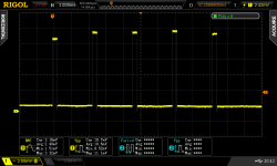
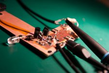
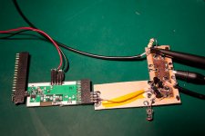
Anyway, let me introduce this guy, I call him Forrest, because he looks retarded, but he does run pretty fast !
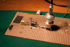
Attached pictures of Forrest and his buddies the current source and NE555 pulse generator.
Scope shots are the transient response to a 23mA current step. Blue is "current" (measured as voltage on the injection resistor), yellow is Forrest's response.
Forrest is built out of a bit of PCB that was laying around (hence the deformed shape), Kaptan tape (chinese version of Kapton) and the "power plane" is a bit of copper tape. It does a nice emulation of a 4 layer board with thin spacing between power/ground planes though, which is the interesting bit here, low inductance. There are 2x 10µ and 2x 1u X7R at the output, maybe they still work, these caps have been desoldered a few times already...
Forrest is dumb so it doesn't have a voltage reference (just a LED). It outputs around 2.4 volts.
The thickness of this copper tape is unknown, but from the price I got it on fleabay (and the label that says "insulating tape") it is probably the thinnest possible kind of stuff. Since Forrest's output impedance is roughly the same as the bit of copper tape... it is a bit of a of problem to measure it here...
As for the transient response, well, I seem to need a faster pulse generator since what this thing is really measuring is the NE555 rise time, not so bad for another old dinosaur, around 30 ns on the fastest part of the edge. The regulator doesn't seem to care, as far as I can see.
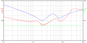
A network analyzer transmission measurement is included. It doesn't give impedance directly (it is transmission relative to 50 ohm). Blue trace is power off (just caps), red trace is regulator powered. The ceramic caps are visible as the two little valleys.
Well, I'm going to make test PCBs for those and order some parts, it seems.
Anyway, let me introduce this guy, I call him Forrest, because he looks retarded, but he does run pretty fast !
Attached pictures of Forrest and his buddies the current source and NE555 pulse generator.
Scope shots are the transient response to a 23mA current step. Blue is "current" (measured as voltage on the injection resistor), yellow is Forrest's response.
Forrest is built out of a bit of PCB that was laying around (hence the deformed shape), Kaptan tape (chinese version of Kapton) and the "power plane" is a bit of copper tape. It does a nice emulation of a 4 layer board with thin spacing between power/ground planes though, which is the interesting bit here, low inductance. There are 2x 10µ and 2x 1u X7R at the output, maybe they still work, these caps have been desoldered a few times already...
Forrest is dumb so it doesn't have a voltage reference (just a LED). It outputs around 2.4 volts.
The thickness of this copper tape is unknown, but from the price I got it on fleabay (and the label that says "insulating tape") it is probably the thinnest possible kind of stuff. Since Forrest's output impedance is roughly the same as the bit of copper tape... it is a bit of a of problem to measure it here...
As for the transient response, well, I seem to need a faster pulse generator since what this thing is really measuring is the NE555 rise time, not so bad for another old dinosaur, around 30 ns on the fastest part of the edge. The regulator doesn't seem to care, as far as I can see.
A network analyzer transmission measurement is included. It doesn't give impedance directly (it is transmission relative to 50 ohm). Blue trace is power off (just caps), red trace is regulator powered. The ceramic caps are visible as the two little valleys.
Well, I'm going to make test PCBs for those and order some parts, it seems.
Attachments


Last edited:
Someone asked :
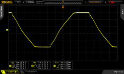
So, I stuck the 10x probe on the transformer secondary.
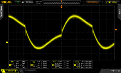
I set trigger to Line, it gives the first picture, as we'd expect, a sine with flattened top and little diode switchoff glitches at the end of the plateau.
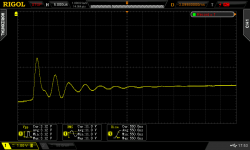
I increased the sensitivity and adjusted the DC offset to zoom on the diode glitch. Then I hit Record and could walk around and expand the time axis at will. Gotta love this scope.
Second shot shows the diode glitch in pornographic detail. There is a bit of ringing, but it's not that bad. Massive poweramp toroids are a different story...
Third shot shows what happens on the second smoothing capacitor : nothing to see here. There is not a hint of high frequency garbage. The output is clean anyway.
If you really can't sleep at night, you can put a snubber 😀
jerry g said:The Jg/subbu psi you recently measured has no Quasimodo style snubber on the transformer secondary.
Would that be overkill? Tia
So, I stuck the 10x probe on the transformer secondary.
I set trigger to Line, it gives the first picture, as we'd expect, a sine with flattened top and little diode switchoff glitches at the end of the plateau.
I increased the sensitivity and adjusted the DC offset to zoom on the diode glitch. Then I hit Record and could walk around and expand the time axis at will. Gotta love this scope.
Second shot shows the diode glitch in pornographic detail. There is a bit of ringing, but it's not that bad. Massive poweramp toroids are a different story...
Third shot shows what happens on the second smoothing capacitor : nothing to see here. There is not a hint of high frequency garbage. The output is clean anyway.
If you really can't sleep at night, you can put a snubber 😀
Attachments
- Status
- Not open for further replies.
- Home
- Amplifiers
- Solid State
- Experimentations on Regulators