It's all ovals.
I am indeed sorry for your straw man's butt.
The hilarity of it!
Your argument is the Straw Man argument.
Occam's Razor
Why do something to simulate a complex load, and not just use the complex load?
Or otherwise should the community perpetuate the idea that this is some kind of black art, and 'experts' can devise a simulation of reality, more effectively that just using the actual load?
It's a very simple premise really.
Not a grain of black arts about it, just merely an exercise in, "look what unnecessary device I can concoct"
A meaningless exercise in self flagellation
In other words:
How does the master of the black arts, simulate the inductance modulation of the loudspeaker voice coil?
And if said expert does not believe that the inductance modulation, the periodic frequency dependant phenomena; has meaningful impact on amplifier performance - where does this idea originate?
In the imagination? Or in scientific experimentation? Or merely assumption that the knowledge he holds is superior, unquestionable, and thus a non issue?
I, for one, are not so bold, nor arrogant, to assume that I know the answer - and I dont believe you have a clue about the answer either.
So, once again, Occam's Razor, Einstein's quote in more recent years
Make the solution as simple as is appropriate, but no simpler.
A reactive network, however complex, is a simplification too far - and a large effort, particularly when the simplest, and most accurate model, is right at your/mine/our fingertips.
Last edited:
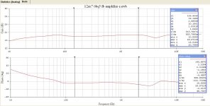
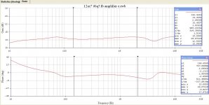
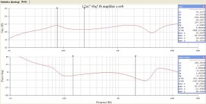
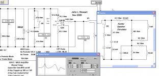
The OPT in the simulation has been corrected so that the results now make sense. I've used sub circuits in the schematic to save space, otherwise they are the same as used previously. So three different conditions, first a normal 8R resister load to establish a base line. Then the two speaker simulator loads for comparison. I've included an example of how a sub circuit appears when called up in the display.
In this case the OPT primary inductance would be typical of a low cost SE amp. As it turns out, increasing the inductance of the OPT increases the height of the LF bump. The 12H choke is already down 3 db at 61 Hz, just below the LF resonance of the test loads.😱
I appreciate Mondogenerator's carefully considered response above. And refer him to post #1, this thread covers amplifier testing, not loudspeakers. Starting a separate thread on loudspeakers would make more sense than here.🙂
Attachments
-
 E2 Schematic with Sub Circuits.JPG95.4 KB · Views: 76
 -
 E2 Resistive Load Gain & Phase.JPG98.7 KB · Views: 78
 -
 E2 Stewart Speaker Simulator Gain & Phase.JPG94.8 KB · Views: 76
 -
 E2 Kantor Speaker Simulator Gain & Phase.JPG101.1 KB · Views: 71
 -
 12AX7 6BQ5 FB Amplifier Schematic with Kantor Load Sub Circuit in Pentode Mode.JPG99.5 KB · Views: 73
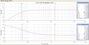
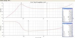
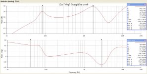
Here are some Phase & Gain Results driving into the Kantor Network via the triode connexion with & without limited (4.9 db) NFB. The pentode as well with 13 db NFB so a comparison is possible to the previous results without NFB.
I found the LF 3db down for the triode was at 16 Hz in previous tests, compared to the much higher rolloff of the pentode connexion.
All looks stable as it usually is running simple FB pairs, whether triode or pentode connected. I've run 20 db NFB with pentode NFB often with no problems at all, even while using the peanut size OPT in AC/DC receivers. Think 6SQ7/50L6.😀
Try adding in some OPT Leakage Inductance next.🙂