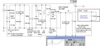
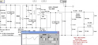
I've done many amplifier simulations in the past but all were into resistive loads. It was time to do the same into something that looks like the real World, a loudspeaker. The speaker simulator circuit I used is what I actually use on the bench during real time tests. The 60 mH inductor is a Hammond choke, The 220 Cap is a non-polarized motor starting cap.
More later, the triode will look much better.😀
More later, the triode will look much better.😀
Attachments
This is interesting to the curious mind, but one small criticism.
60mH is huge L for a loudspeaker, 220uF equally ridiculous in size - even taking into account of a complex crossover.
It illustrates your point well, but by hugely exacerbating effects due to unrealistic reactances.
More useful would be a model of two paralle summed 2nd order transfer functions, since most loudspeakers (I guess) utilise a 2nd order network.
5mH L and 68uF may, in that case, be more appropriate for typical max values.
The effect of the erroneously named Zobel, Impedance equaliser circuits that can be used in passive crossovers, could then show the benefits in valve amplification, as a comparison
Last edited:
Here's the network that Stereophile uses, a bit more complex.
Real-Life Measurements Page 2 | Stereophile.com
Real-Life Measurements Page 2 | Stereophile.com
Here's the network that Stereophile uses, a bit more complex.
Real-Life Measurements Page 2 | Stereophile.com
Yes, I'm aware of that one, it has been doing the rounds for quite a while. He also uses a very large NP cap & a few mH choke to get the simulator resonance below 100 Hz. 10 &12 inch speakers in a sealed box often have a single resonance in that range.🙂
A ported box normally has a double peak. This version was convenient for me, I already had the parts. Better still, it works on the bench & no ear splitting sound.😀
How about the electrical effect of airwaves bouncing back at the speaker cone? (at 100+dB please). You will be rewarded with a permanent wave, instantly 😀 And there is a Petit Churchhill in it from me.
Sounds like a plan, but I've already run resonance curves on many boxes beginning while I worked in the research lab 60+ yrs ago. So I have seen plenty of data to shew that the path I take works! How many speaker resonance curves have you run? In open air, no external reflections.😀Now back to another simulation. Watch this space for the next episode.🙂
...60mH is huge L for a loudspeaker, 220uF equally ridiculous in size - even taking into account of a complex crossover.....
I don't think jhstewart9 is modeling a crossover. Look at his impedance plot. Sure looks to me like a simple speaker. A bass bump and a treble rise. Any speaker bigger than your hand, the speaker Moving Mass is indeed hundreds of uFd on the electric side; stiffness is many mH (depends much on box size).
Ignoring Stereophile's crossover, and given the many different speakers available, I don't see a fundamental difference between the two models. 7.5r 5.6r? 220u 500u? 60mH 10mH?
Airwaves bouncing back? "at 100+dB please"??? How does SPL even matter? (Air is linear even at 100dB SPL.) And much lighter than a cone.
jhstewart9's model was plenty good in days when this stuff mattered (1920s-1930s). Maybe too good for his purpose: at least for single tones, any relative impedance can be hit with a single reactance and careful choice of frequency.
Attachments
Well, one could imagine there is a difference in air pressure before and behind a moving cone. From a physical view one can imagine the displacement of the cone going outwards has a force to overcome both by extending the suspension and creating a small under pressure in a sealed cabinet. Moving backwards the travel would be lighter.Air is linear even at 100dB SPL And much lighter than a cone.
As PRR has noted, this is not a cross over network. The intention is to simulate a real speaker load to test its effect on triodes & pentodes as output tubes. And with these results to understand why designing a NFB network is a daunting proposition while still maintaining amplifier stability.
Since the advent of the Williamson with its 20 db of NFB that seems to have been the Holy Grail for a majority of amp builders. Williamson used a triode output stage whose natural damping results in only small change of stage gain while driving a complex load.
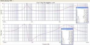
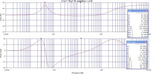
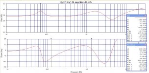
Pentodes are current devices, their stage gain will closely follow the impedance of the load. If one looks at that hump at LF on the first response curves we see a rise of 15 db. So if 20 db had been set on this amplifier using a resistive load the NFB would be 35 db at that hump. This simple amp if built in real hardware is probably safe. Must PP amp would run out of stability margin & intermittent oscillation might occur.🙂
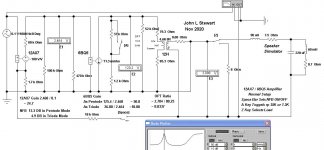
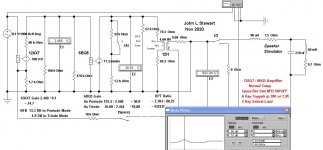
The 60 mH choke is a Hammond 159ZC. The new schematic includes the coil DC resistance of 0.7R but changes the end result little. The 7.5R resister is a multiple, paralleled thing to reduce inductance, good for about 50 Watts.
For the OPT I've shewn some winding resistances, they are at DC. Because of skin & proximity effects the real AC resistance is somewhat higher. I've also included in the simulation a parallel 52K resistor to sim some hysteresis & eddy current losses in the OPT iron core.
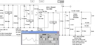
The concept of duality in electrical networks allows us to replace a real voltage source with its series resister with a real current source with a like value of resistor in parallel. So altho the triode connected 6BQ5 should be represented by a voltage source I've put it equivalent current source generator into the test circuit instead. That way only its load resister needs to be switched from 38K to 1.2K by the switch 'A'. Of all the 6BQ5/EL84 data sheets I checked none shewed a value for triode rp. The value 1.2 K was taken from the plate family graph on one of those sheets.
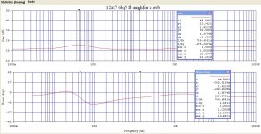
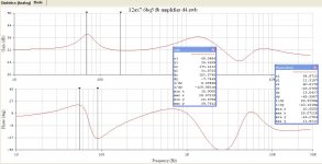
The frequency results traces for pentode & triode are displayed on the same scale. So triode gain is quite a bit less as shewn down the sheet somewhat. But the LF bump is a lot smaller, the triode circuit would be much easier to deal with sofar as NFB is concerned.🙂
And yes, I've worked on some PA systems too. And built a few amplifiers for them way back when I was interning & needed some extra $$$. (Gelt)
I think Painted was talking about standing waves.😀
Since the advent of the Williamson with its 20 db of NFB that seems to have been the Holy Grail for a majority of amp builders. Williamson used a triode output stage whose natural damping results in only small change of stage gain while driving a complex load.
Pentodes are current devices, their stage gain will closely follow the impedance of the load. If one looks at that hump at LF on the first response curves we see a rise of 15 db. So if 20 db had been set on this amplifier using a resistive load the NFB would be 35 db at that hump. This simple amp if built in real hardware is probably safe. Must PP amp would run out of stability margin & intermittent oscillation might occur.🙂
The 60 mH choke is a Hammond 159ZC. The new schematic includes the coil DC resistance of 0.7R but changes the end result little. The 7.5R resister is a multiple, paralleled thing to reduce inductance, good for about 50 Watts.
For the OPT I've shewn some winding resistances, they are at DC. Because of skin & proximity effects the real AC resistance is somewhat higher. I've also included in the simulation a parallel 52K resistor to sim some hysteresis & eddy current losses in the OPT iron core.
The concept of duality in electrical networks allows us to replace a real voltage source with its series resister with a real current source with a like value of resistor in parallel. So altho the triode connected 6BQ5 should be represented by a voltage source I've put it equivalent current source generator into the test circuit instead. That way only its load resister needs to be switched from 38K to 1.2K by the switch 'A'. Of all the 6BQ5/EL84 data sheets I checked none shewed a value for triode rp. The value 1.2 K was taken from the plate family graph on one of those sheets.
The frequency results traces for pentode & triode are displayed on the same scale. So triode gain is quite a bit less as shewn down the sheet somewhat. But the LF bump is a lot smaller, the triode circuit would be much easier to deal with sofar as NFB is concerned.🙂
And yes, I've worked on some PA systems too. And built a few amplifiers for them way back when I was interning & needed some extra $$$. (Gelt)
I think Painted was talking about standing waves.😀
Attachments
-
 12AX7 6BQ5 FB Amplifier Response to Complex Load in Pentode Mode B.JPG136.1 KB · Views: 117
 -
 12AX7 6BQ5 FB Amplifier Schematic with Complex Load in Pentode Mode W Caption B.JPG92.1 KB · Views: 125
 -
 12AX7 6BQ5 FB Amplifier Response to Complex Load in Triode Mode.JPG141.9 KB · Views: 124
 -
 12AX7 6BQ5 FB Amplifier Schematic with Complex Load in Triode Mode.JPG92.8 KB · Views: 142
> talking about standing waves.
Even in PA systems.... you have <5% coupling from electricity to air, and <5% coupling from air to electricity. Even if the box were lossless only about 0.0025 or 1/400th of the electric input can kick-back to the electric side.
Electro-mechanical coupling can be very much better, which is why the moving mass looks-like a much larger capacitor than we expect.
Running out of room on that schematic but it is possible to create a sub-circuit that requires little space. Just a 2-terinal box with all of the parts of the Ken Kanter simulator inside, I'll try that when the weather goes for a crap here in a few daze.
Still much to do outside before more snow, running out of time.🙁
Still much to do outside before more snow, running out of time.🙁
Is the conclusion justified that triodes act as a voltage device, or is it more that their imperfect current behavior is turned into an advantage given this NF situation?As PRR has noted, this is not a cross over network. The intention is to simulate a real speaker load to test its effect on triodes & pentodes as output tubes. And with these results to understand why designing a NFB network is a daunting proposition while still maintaining amplifier stability.
...
Pentodes are current devices, their stage gain will closely follow the impedance of the load.
...
The frequency results traces for pentode & triode are displayed on the same scale. So triode gain is quite a bit less as shewn down the sheet somewhat. But the LF bump is a lot smaller, the triode circuit would be much easier to deal with sofar as NFB is concerned.
I dont think anyone is modelling a crossover either
PRR, as is usual, you have grabbed the **** end of my point and twisted it.
That impedance network is not representative of reality, in any way at all.
Sure, we want to simulate the resonance of a loudspeaker.
Usually this includes the lumped parameters of the enclosure, and crossover.
So facetiousness aside; its far easier to cannibalize a damaged loudspeaker, cut away the cone membrane, and mount a sensible weight onto the end of the voice coil, simulating the mass of the membrane.
Then add appropriate crossover components.
Voila! Realistic load.
That impedance network is not representative of reality, in any way at all.
Let me know what network you propose & I'll stuff it into this test.🙂
The network I use in hardware is meant to be simple & sims worst case. If the amp passes this one it is probably OK.😀
So here is the response to the Kantor Network, sans Zoebel Network.The LF hump appears to be only 8 db (x1, y1 & x1, y2) in this case, held down by the 39R resistor across the LF network across its L & C.
Attachments
I just did...its in the post above ^^^
The best loudspeaker test load, is um...a loudspeaker.
But I get the gist, it would certainly represent a worst case scenario, rather a worse than ever likely to be encountered, worse case scenario.
(I'd guess excepting ESL or something, and that is something outside my realms of knowledge)
All of the electrical parameters can be attributed to components, but why bother?
Its far easier to have the loudspeaker, in its native environment, modulating inductance and all, and providing the Fs resonance impedance peak/s.
Can you imagine the complexity of the network required to simulate the impedance characteristic of...for example, a transmission line, QWTL, front loaded horn, for example?
In the case of the latter, Horn loaded, which would be most likely to be used with a lower power valve amplifier, I feel it would be painful to emulate multiple impedance peaks due to resonance, or harmonics of fundamental resonance, purely in components
But then, some folks get a thrill out of masochism ��
It's all ovals.
Pure R, ot at a resonance, the oval degrades to a straight line.
Assuming there's no 1-way diode in the speaker. That would be dumb, and a speaker fault not the amplifier's problem.
I am indeed sorry for your straw man's butt.
Pure R, ot at a resonance, the oval degrades to a straight line.
Assuming there's no 1-way diode in the speaker. That would be dumb, and a speaker fault not the amplifier's problem.
I am indeed sorry for your straw man's butt.
So here is the Zoebel Network put back into Ken Kantor's speaker simulator. As predicted the HF rolloff starts at 10 Khz. Not sure why he put the Zoebel Network into the Sim, it would normally be part of the amplifier, not the load. The Zoebel Network is switched in or out by key X.
The Gain response graph gain has been increased to 30 db FS to better see the bumps in the response.
The Gain response graph gain has been increased to 30 db FS to better see the bumps in the response.
Attachments
The LF response should be down 3 db at 61 Hz if the OPT is really 12H driving the pri/sec ratio & 8R load I used. Its not down at all. Think I've got an error in the OPT model or the way it is used.
Can't do thatt today, its time to fix the Coleman generator. The carb is plugged up, a Tecumseh engine from 2003.😱
Can't do thatt today, its time to fix the Coleman generator. The carb is plugged up, a Tecumseh engine from 2003.😱
- Home
- Amplifiers
- Tubes / Valves
- Example Simulations Driving Complex Loads