I can't measure, almost every touch with the probe causes oscillation... 😱
Tried caps untill the 1nF values...
(Servo not used yet!)
But anyway I guess it should work even if its not ideal for distortion.
Tried caps untill the 1nF values...
Yeah, that's what I exactly dont understand and posted in my previuse post which I guess you just missed.If the VBE of you NPN was so inferior to the one of your PNP, we could understand the second
stage of the diamond (negative rail side) can not reach enough voltage to turn in.
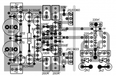
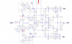
I checked it a million time, but maybe I'am just missing the same thing, please somebody review my PCB in the attachment.So, you made a mistake in cabling somewhere, verify from scratch.
(Servo not used yet!)
I like to run the BCs on higher currents my initial goal was about 5-6mA.With your CSS typology, the value of the adjustable resistance to feed 1.55mA to the input transistors is simulated around 420 Ohms in my LTSpice.
But anyway I guess it should work even if its not ideal for distortion.
Attachments
I don't understand why you want to treat all the problems at once... with an incomplete amp.I can't measure, almost every touch with the probe causes oscillation... 😱
1- Remove the VAS.
1- Verify your CSS are working as expected.
3- Fix the input stage first (alone and quietly).
4- Complete the all amp (VAS+output) and fix last problems if any. (protecting your output devices by resistances in the rails.
(I tried to sim my amp without the output devices: this is nonsense ;-)
I should try to look at your P.B., but it is obviously not the same as the schematic. Please, provide a complete schematic in accordance to it. Too much work to reverse.
Last edited:
I attached them and removed the "C multiplier" PS section from the PCB which is not present on the schematic.
I think an IPS should work this way without the OPS at least for setting the DC bias first.
I usually test them this way (even with low impedance FB amps like this CFA as well).
I think an IPS should work this way without the OPS at least for setting the DC bias first.
I usually test them this way (even with low impedance FB amps like this CFA as well).
Attachments
Should! 😉
Anyway sorry but I am completely new to diamonds and still unsure why this should work at all.
As I see if I assume the Vbe-es of the 1st 4 tranies are all different the bias should be randomly settled.
And as my CCS works at least @ 3mA the 1st stage get warmer and the Vbe drops and thats why even the
2nd stage isnt turning on really and their currents are also decreasing after switch on from 2mA to almost 0...
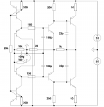
I tried to search for how a diamond biasing works and found Walt Jungs article and schematic as attached.
He also says that the bias can/should be setup with the ratio of the helping resistors labeled as R3/R4 and R6/R7.
Link: http://waltjung.org/PDFs/WTnT_Op_Amp_Audio_2.pdf
Please somebody explain! 🙂
Anyway sorry but I am completely new to diamonds and still unsure why this should work at all.
As I see if I assume the Vbe-es of the 1st 4 tranies are all different the bias should be randomly settled.
And as my CCS works at least @ 3mA the 1st stage get warmer and the Vbe drops and thats why even the
2nd stage isnt turning on really and their currents are also decreasing after switch on from 2mA to almost 0...
I tried to search for how a diamond biasing works and found Walt Jungs article and schematic as attached.
He also says that the bias can/should be setup with the ratio of the helping resistors labeled as R3/R4 and R6/R7.
Link: http://waltjung.org/PDFs/WTnT_Op_Amp_Audio_2.pdf
Please somebody explain! 🙂
Attachments
Last edited:
Pairing VBE of transistors for Diamonds is a common and recommended practice. That is, of course, what i did on my prototype. While they were all very close.Should! 😉
Pairing is something you always have to do, even with simple input stages in order to minimize Offset.
An other reason why i use 1.5 mA is VBE of NPN/PNP are closer at low bias.
I can't imagine you should had the bad luck two times to have both NPN and PNP of the second stage of your diamond so higher than in its complementary device in first stage that both don't turn on ? The servo is supposed to take care of their unbalances, too. An amp is a whole, why do you think i'm insisting you debug your amp all finished ?
1- Build and verify your CSSs.
2- Build and verify your Diamond.(no VAS connected).
3 -Finish your amp and debug (they always oscillate at this point ;-)
You are loosing a lot of time, turning in circles.
By the way, why do you want the quiescent of your input tranies so hot, you want to use-it for radio frequencies ?
Ok, then I'll measure my Vbe-s to figure it out. (I didn't match them in pairs...)
0: Servo: as I searched for diamond topology I barely saw servos,
so I guess it should work, max it will have a few mV DC offset.
1: The CCS-es seems to work for me (based on the current sensing 4R7s).
2: I dont see the point/benefit removing the VAS now as they arent open at all.
4: high currents: higher speed, higher beta.
Hi Guys
Cortez - Most diamond amps do have servos, but they can be made without them. See Bonsai's site Hifisonix and look at his sx and nx amp articles - both the same front end and simpler than what is presented here.
Yes, the front end should be able to operate on its own. Without the emitter Rs, it will be difficult to get it to settle even with matched devices. The REs give some compliance in the voltage differences between the devices and help move them to the operating points you want them at.
Jung's article is an output stage, so REs are lower in value than you see in the CFA examples for front-end diamonds. Cooler operation of the diamond BJTs promotes quicker settling and more settled performance over time. To this point one should try to shield the input stage from the heat of the output stage.
Have fun
You are perfectly right.Yes, the front end should be able to operate on its own. Without the emitter Rs, it will be difficult to get it to settle even with matched devices. The REs give some compliance in the voltage differences between the devices and help move them to the operating points you want them at.
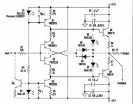
Some tunings can be made in my schematic to can afford all the situations. Replacing R36 and R43 by a 100 Ohm potentiometer to adjust the currents of the second stage, as an example.
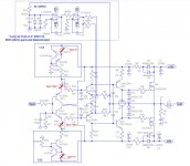
Ok, I have worked a little to help this diamond with high VBE disparate devices.
See attached.
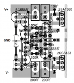
Construction tip: First build your CSS and the first input stage stage.
Tune your CSS to get 150mv DC between the R25/R26 ends.
Build the second stage of your diamond. Adjust R36/R40 to get 70.5 mV between the ends of R23/R24.
Now your diamond input is balanced with 1.55mA in each transistor.
If you want higher currents it is at your own risks. ~1.5mA is optimal.
I greatly recommend you exchange each of R36/R40 adjustables, once set and amp finished, by 2 fixed metal film resistances of the same values than each of them.
See attached.
Construction tip: First build your CSS and the first input stage stage.
Tune your CSS to get 150mv DC between the R25/R26 ends.
Build the second stage of your diamond. Adjust R36/R40 to get 70.5 mV between the ends of R23/R24.
Now your diamond input is balanced with 1.55mA in each transistor.
If you want higher currents it is at your own risks. ~1.5mA is optimal.
I greatly recommend you exchange each of R36/R40 adjustables, once set and amp finished, by 2 fixed metal film resistances of the same values than each of them.
Attachments
Last edited:
He also says that the bias can/should be setup with the ratio of the helping resistors labeled as R3/R4 and R6/R7.
I found the exact same solution of these 4 resistors (have mentioned this in earlier post I believe) without knowing about Jungs article. I have written in my note somewhere regarding how to make these things work. Unfortunately my computer is broken now so I cannot contribute, but I hope you continue with your work so we can make it better. I started with Esperado circuit, but don't know how much differences that I have made from that, may be completely different.
There is some annoyances with this solution.I found the exact same solution of these 4 resistors
We do not have any more the unique return path for the feedback: any unbalance between R6 & R12 or R23 & R24 will increase distortion. The necessity of tuning is not a good solution for an industrial process. Adjustable resistances are not optimal, for both sound quality and long lasting.
I will look at a servo acting on CSS in the next days. Not so easy at first sight.
There is some annoyances with this solution.
We do not have any more the unique return path for the feedback: any unbalance between R6 & R12 or R23 & R24 will increase distortion.
But there is still a lot to gain without varying the top and bottom resistance. Actually that was how I did it, R3=R4 and R6=R7.
The necessity of tuning is not a good solution for an industrial process.
This is also not a problem for DIY.
Adjustable resistances are not optimal, for both sound quality and long lasting.
Not a problem also for DIY to use real resistors.
I will look at a servo acting on CSS in the next days. Not so easy at first sight.
There is a trick in how to use those resistors so to help minimize the offset. The whole idea (in my case, don't know with Jung) of these resistors was to avoid the servo. I don't know, I have no chance to ABX the effect of servo but if I can get away without servo then I will not use a servo... intuitively.
No need of ABX, omho. Well designed, a servo don't add noise or distortion in the audio band, and you can both avoid litycs and get an effective action so slow in frequency that even the phase's rotations are null at 16 Hz.I don't know, I have no chance to ABX the effect of servo but if I can get away without servo then I will not use a servo... intuitively.
The only problem here is we would need two servos, one for the polarization of the diamond, one for the offset. And find a way for they don't fight against each other.
Thank you guys for your effort, unfortunately I dont have the time right now for the DVSSA project maybe a bit later hopefully.
- Status
- Not open for further replies.
- Home
- Amplifiers
- Solid State
- Evolution of the VSSA? Esperado's DVSSA...