What I dont understand, why is such a thing placed on the board in the middle of sensible curcuits
Wouldnt it be better placed between board and output terminals
Well, maybe its obvious I have no idea what its about😱
But I am interested because my next woofer amps might be classD
And I have always thought the used output inductors looked pretty awful
Wouldnt it be better placed between board and output terminals
Well, maybe its obvious I have no idea what its about😱
But I am interested because my next woofer amps might be classD
And I have always thought the used output inductors looked pretty awful
Last edited:
The leakage comes from imperfections, for example when you wind the turns in a way that it goes around along the core, then you make a single turn choke in excess the toroid. Not equal distances are the other source of leakage.
Even if a toroidal coil is wound perfectly it still has one single loop that is causing a stray field. And this is unavidable. Don't forget about that !
Regards
Charles
I didn't forget, I wrote about it! (Maybe I wasn't totally clear.) But actually it is avoidable! With two layers. Or it can be minimized with only one layer, if you split the coil into two symmetric halves, then connect them paralell (very small values) or series (higher values). You can decrease it further, use your imagination!
if you can't contain it shield it?
I thought the same thing and started placing them under the PCB into one of those small shielded boxes you can get and earthing it to the case... which is in turn earthed to the UK third pin.... no idea if it makes any difference but I feel better for doing it 😀
What I dont understand, why is such a thing placed on the board in the middle of sensible curcuits
I thought the same thing and started placing them under the PCB into one of those small shielded boxes you can get and earthing it to the case... which is in turn earthed to the UK third pin.... no idea if it makes any difference but I feel better for doing it 😀
Attachments

Charles!
Another simple way to eliminate the flux leakage caused by the loop: before winding the coil make a loop in the other direction!
Another simple way to eliminate the flux leakage caused by the loop: before winding the coil make a loop in the other direction!
Another simple way to eliminate the flux leakage caused by the loop: before winding the coil make a loop in the other direction!
You're still under the misconception that you can eliminate the flux leakage entirely. Let me assure you cannot. And while that may not make a difference in low frequency applications, it certainly does in high frequency ones like this.
The traditional advice for output trafos in class-D is to use heavily cored and heavily shielded trafos. Stick to it.
You're still under the misconception that you can eliminate the flux leakage entirely. Let me assure you cannot
No, obviously I haven't said (or thought) this. Please try to understand what I wrote! Simply denying is pointless.
What is your problem exactly? Does the knowledge about leakage mechanism hurt you? Do you sell magnetic shields? Or what?
The traditional advice for output trafos in class-D is to use heavily cored and heavily shielded trafos. Stick to it.
I don't know why have you told this, and what does it mean.
I don't know why have you told this, and what does it mean.
It means that high frequency operating cores like in the output of a class-D will always function best the less parasitic resistance and capacitance it has, both are ensured by correctly coring the trafo. Air cores of any type should be avoided at all cost to achieve the best sound.
ClassD what? ClassD amplifier? Then why did you write trafo? ClassD power supply (it contains trafo indeed)? How does it come here?
Parasitic resistance and capacitance of a core? I think you are lost somewhere!
Doubtfully. You forgot about many important things.
And by correctly wind it, with the correct wire, with the correct insulation.
Tell this to Sendler, I'd ended up the idea of using air core many years ago! (Unless it's for an induction heater.)
Parasitic resistance and capacitance of a core? I think you are lost somewhere!
always function best the less parasitic resistance and capacitance it has
Doubtfully. You forgot about many important things.
both are ensured by correctly coring the trafo
And by correctly wind it, with the correct wire, with the correct insulation.
Air cores of any type should be avoided at all cost to achieve the best sound.
Tell this to Sendler, I'd ended up the idea of using air core many years ago! (Unless it's for an induction heater.)
ClassD what?
Output coil! If you don't understand that this is the class-D forum, and as such any discussion about cores and coils herein would be relevant only to the output filter coil(s), then I can't help you further.
Last edited:
Type 2 cores do not SOUND better
Sorry. Measurements and theory aside, my air cores sound way better than my type 2 toroids in the output filter of a Sure 2X100 amp. Same wire.Air cores of any type should be avoided at all cost to achieve the best sound.
Saturnus! If you don't know that trafo, core and coil are not the same things, then please don't "help"!
Sendler! With the same inductance?
Sendler! With the same inductance?
Sorry. Measurements and theory aside, my air cores sound way better than my type 2 toroids in the output filter of a Sure 2X100 amp. Same wire.
"cable effect"? 😀
Seriously though, I'm sure you think they do, and maybe they do because you had a lucky day winding them and that the original where completely lousy quality, which they are, but all things being equal cored output coils sound better and measures better than air cores.
Parasitic capacitance
Tell me: Why are air core inductors produced?
Least parasitic capacitance: One layer coil wound on a plastic former.
Least resistance: Enough copper.
It means that high frequency operating cores like in the output of a class-D will always function best the less parasitic resistance and capacitance it has, both are ensured by correctly coring the trafo. Air cores of any type should be avoided at all cost to achieve the best sound.
Tell me: Why are air core inductors produced?
An externally hosted image should be here but it was not working when we last tested it.
Least parasitic capacitance: One layer coil wound on a plastic former.
Least resistance: Enough copper.
Even if a toroidal coil is wound perfectly it still has one single loop that is causing a stray field. And this is unavidable. Don't forget about that !
Regards
Charles
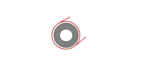
It is not uncommon to have a single anti-turn on the PCB that cancels the single loop formed by the toroid. It's not perfect, but it can be quite effective. for a core who's axis is parallel to the PCB, this can be accomplished with a loop of wire, or for better cancellation, two parallel loops on either side of the toroid.
John
Differences
Let's see what these monsters will do. They turned out quite large due to the 14ga wire.

There are other variables in play for me to make sweeping statements but eventually I will address all of the differences and feel confident that the class D filters will follow the experience of speaker designers who learned years ago that air cored inductors sound better than magnetic cores especially when we are stuck with using them in series with our tweeters. I have 6uH for the T106-2 and 4uH for the solenoidal air core so you are right. I am still dealing with substantial variables. As it often happens here, we start with a simple question in a thread which eventually degenerates somewhat to where the posts start to get defensive of each view point. It is apparent to me after many posts and threads over the last month that there have been very few reports by people doing listening trials with various coils. The ones that did report improvements are using air cores until they are warned about the EMI. This lack of comparrisons still surprises me as caps have been discussed ad nauseam everywhere but maybe class D is still much smaller in interest that not nearly as many serious DIYers are trying to push their sonic envelope as much as we see in the solid state forum. The emission problem also creates a log jam for the styles that can be implemented. Tripath seems to have done some listening and settled on the type 2 core with 22guage wire at 12uH but most manufacturers have a high priority on miniaturization which I do not.With the same inductance?
Let's see what these monsters will do. They turned out quite large due to the 14ga wire.
Best Toroid for Class D
According to Ferroxcube, a gapped toroid is the preferred coil form (which they sell, of course). The gap helps the core by storing more energy in the gap and preventing saturation of the core. If the core saturates, the inductance collapses.
They have an app. note where an IR class D amp had the output inductors were replaced with gapped toroid coils and the audio distortion measured was noticeably lower. Makes sense to me but I'm an engineer.
So who sells Ferroxcube cores
So who sells Ferroxcube cores I can try?
.According to Ferroxcube, a gapped toroid is the preferred coil form (which they sell, of course). The gap helps the core by storing more energy in the gap and preventing saturation of the core. If the core saturates, the inductance collapses.
They have an app. note where an IR class D amp had the output inductors were replaced with gapped toroid coils and the audio distortion measured was noticeably lower. Makes sense to me but I'm an engineer.
So who sells Ferroxcube cores I can try?
Speaker xo is where I come from
And there the ordinary air coil is the best
But when biggies are needed toroids are the best
Some are air gapped, but not sure how its done
A few are special ironpowder toroid core containing enough air to function alike air gapped
I dont really like foil inductors, but with such small inductor needed here this makes me wonder if it would be useable combined with a toroid core
toroid core foil inductor
But it may not have the minimal interference radiation of a wirewound toroid 😡
Attachments
Last edited:
Try this.
http://www.ferroxcube.com/appl/info/gaptoroids.pdf
Use a TN26/11-3C20-A113 if you are going to order some. It is the largest and will handle 100W or so. Read the app. note and find out why you want the big one.....
Ferroxcube can be bought at their distributors but I see no stock on the above PN at any of their distributors. Bummer. I am going to need (4) pcs soon.
- Status
- Not open for further replies.
- Home
- Amplifiers
- Class D
- Ever tried the type 0 toroids?