I will be off keyboard for a week more or so, thus I wish for the coming New Year everyone to achieve (or retain) the most valuable targets in life.
May we all be able to enjoy our hobby too.
George
May we all be able to enjoy our hobby too.
George
Hey guys, happy holidays!
I just got the holes cut for my drivers, and the drivers are on their way. In a surprise twist, I ordered a pair of Tangband W3-926SDF:
Tang Band W3-926SDF 3" Full Range Speaker 264-912
...But I plan to experiment with some other drivers later using the same cabinets. All that's left for me to do is either print out some plans or just draw the design onto the panels before I start gluing. Hopefully I will be done by the time the TBs arrive. More to come soon!
-Chaz
Last edited by a moderator:
Chaz,
Good luck with getting the channels glued. What size cornu were you making? The driver you ordered looks like it should work well - looks nice too.
Happy holidays.
Good luck with getting the channels glued. What size cornu were you making? The driver you ordered looks like it should work well - looks nice too.
Happy holidays.
Here is an updated version of the AkAbak script I posted in the other thread some time back. It now accounts for baffle diffraction, horn outlet displacement and direction, and has a wall behind it. The main use for such a script is to determine if a given set of horn dimensions will provide correct bass reinforcement for a given driver. It'll need work to add stuffing to the back chamber and HF losses in the horns before it can be trusted above a few hundred Hertz. Note that it's still "half a Cornu" - only one set of horn paths is modeled. The other half is a mirror of the first half so is just folded onto (added to) the first half. I still have my reservations about the performance of the "split length horns" - I still think you would be better off designing an optimum back-loaded horn in Hornresp or MJK spreadsheets, then plotting it into a spiral yourself.
Handy hint: If you want to see what the actual dimensions are for any of the elements, do the following:
1. Put the cursor somewhere in the text of the element (for example, in a Radiator element).
2. Select Net --> Acoustic -> Radiator...
3. The element editor will open. All of the substituted values will be displayed as actual values. For the 'Horn 3 mouth' radiator above, the "y" value will be displayed as 35cm.
This is very handy for debugging when you're working with formulas.
Code:
| Cornu style horn.
| Model developed by printing Dave's PDF and measuring
| the path lengths and widths. The printed version was 23.3 cm wide,
| so it is scaled up to the required width.
| For example, a 70 cm horn is 70 / 23.3 = 3 times as large,
| so the dimensions are scaled up by 3.
| This version has the horns exiting at the sides, and is mounted on a wall.


Def_Const
{
| Required inputs:
| ================
| Horn width and height in centimetres (square baffle)
| Horn depth (wall height) in centimetres
| Driver Thiele-Small parameters (in Def_Driver further down)
| Do not delete the semi-colons;
Horn_Width = 70;
Horn_Depth = 11.5;

| All dimensions are converted to the AkAbak default unit (metres)
| and scaled up. Horn segment areas are doubled because there are
| 2 of each horn segment.
Scale = Horn_Width / 23.3;
Depth = Horn_Depth * 1e-2;
Tcvol = Depth * Scale * 4.5e-2 * Scale * 4.7e-2;
SxDx2 = Scale * Depth * 2;
Width = Horn_Width * 1e-2;

H1S1  = SxDx2 * 0.75e-2;
H1L12 = Scale * 2.5e-2;
H1S2  = SxDx2 * 1.0e-2;
H1L23 = Scale * 5.0e-2;
H1S3  = SxDx2 * 1.2e-2;
H1L34 = Scale * 12.0e-2;
H1S4  = SxDx2 * 1.5e-2;

H2S1  = SxDx2 * 0.7e-2;
H2L12 = Scale * 3.2e-2;
H2S2  = SxDx2 * 1.0e-2;
H2L23 = Scale * 6.2e-2;
H2S3  = SxDx2 * 1.3e-2;
H2L34 = Scale * 5.0e-2;
H2S4  = SxDx2 * 2.3e-2;
H2L45 = Scale * 7.3e-2;
H2S5  = SxDx2 * 2.5e-2;
H2L56 = Scale * 6.6e-2;
H2S6  = SxDx2 * 2.6e-2;
H2L67 = Scale * 10.8e-2;
H2S7  = SxDx2 * 6.6e-2;

H3S1  = SxDx2 * 0.8e-2;
H3L12 = Scale * 1.4e-2;
H3S2  = SxDx2 * 1.5e-2;
H3L23 = Scale * 5.1e-2;
H3S3  = SxDx2 * 1.6e-2;
H3L34 = Scale * 3.9e-2;
H3S4  = SxDx2 * 1.8e-2;
H3L45 = Scale * 7.0e-2;
H3S5  = SxDx2 * 2.1e-2;
H3L56 = Scale * 17.4e-2;
H3S6  = SxDx2 * 2.6e-2;
H3L67 = Scale * 11.3e-2;
H3S7  = SxDx2 * 6.6e-2;

}

| Specify your driver here. You can use AkAbak's Def--> Def_Driver
| tool to enter the parameters.

Def_Driver  'FF125K'
SD=66.5cm2   |Piston
fs=72Hz
Vas=9.12L
Qms=9.04
Qes=0.27
Re=7.2ohm
Le=0.73mH
ExpoLe=1

Def_Driver  'TC9FD'
SD=36.3cm2   |Piston
fs=123Hz
Mms=2.43g
Qms=2.6
Qes=1.5
Re=6.3ohm
Le=0.1mH
ExpoLe=1

| The wall behind the speaker.
Def_Reflector  Wall={Depth}
  HAngle=0  VAngle=0


System 'Cornu Spiral'

| Enter the name of your defined driver.
|=======================================
Driver Def='FF125K' 'Driver 1'
Node=1=0=3=4

Radiator 'Front_Rad'
Def='Driver 1'
Node=3
x=0  y=0  z=0
HAngle=0  VAngle=0
WEdge={Width / 2}
HEdge={Width / 2}
Reflection

Enclosure 'Driver Chamber'
Node=4
Vb={Tcvol}
Lb={Depth}

Waveguide 'Horn 1 seg 1'
Node=4=5
STh={H1S1}
SMo={H1S2}
Len={H1L12}
Conical

Waveguide 'Horn 1 seg 2'
Node=5=6
STh={H1S2}
SMo={H1S3}
Len={H1L23}
Conical

Waveguide 'Horn 1 seg 3'
Node=6=7
STh={H1S3}
SMo={H1S4}
Len={H1L34}
Conical

Waveguide 'Horn 2 seg 1'
Node=7=21
STh={H2S1}
SMo={H2S2}
Len={H2L12}
Conical

Waveguide 'Horn 2 seg 2'
Node=21=22
STh={H2S2}
SMo={H2S3}
Len={H2L23}
Conical

Waveguide 'Horn 2 seg 3'
Node=22=23
STh={H2S3}
SMo={H2S4}
Len={H2L34}
Conical

Waveguide 'Horn 2 seg 4'
Node=23=24
STh={H2S4}
SMo={H2S5}
Len={H2L45}
Conical

Waveguide 'Horn 2 seg 5'
Node=24=25
STh={H2S5}
SMo={H2S6}
Len={H2L56}
Conical

Waveguide 'Horn 2 seg 6'
Node=25=26
STh={H2S6}
SMo={H2S7}
Len={H2L67}
| Conical
T=1

Radiator 'Horn 2 mouth'
Def='Horn 2 seg 6'
Node=26
| Exits top right, pointing right.
x={Width / 2}  y={Width / 4}  z={-Depth / 2}
HAngle=90  VAngle=0
WEdge={Width / 4}
HEdge={Depth / 2}
Reflection

Waveguide 'Horn 3 seg 1'
Node=7=31
STh={H3S1}
SMo={H3S2}
Len={H3L12}
Conical

Waveguide 'Horn 3 seg 2'
Node=31=32
STh={H3S2}
SMo={H3S3}
Len={H3L23}
Conical

Waveguide 'Horn 3 seg 3'
Node=32=33
STh={H3S3}
SMo={H3S4}
Len={H3L34}
Conical

Waveguide 'Horn 3 seg 4'
Node=33=34
STh={H3S4}
SMo={H3S5}
Len={H3L45}
Conical

Waveguide 'Horn 3 seg 5'
Node=34=35
STh={H3S5}
SMo={H3S6}
Len={H3L56}
Conical

Waveguide 'Horn 3 seg 6'
Node=35=36
STh={H3S6}
SMo={H3S7}
Len={H3L67}
| Conical
T=1

Radiator 'Horn 3 mouth'
Def='Horn 3 seg 6'
Node=36
| Exits top left, pointing up
x={-Width / 4}  y={Width / 2}  z={-Depth / 2}
HAngle=0  VAngle=90
WEdge={Width / 4}
HEdge={Depth / 2}
Reflection
Handy hint: If you want to see what the actual dimensions are for any of the elements, do the following:
1. Put the cursor somewhere in the text of the element (for example, in a Radiator element).
2. Select Net --> Acoustic -> Radiator...
3. The element editor will open. All of the substituted values will be displayed as actual values. For the 'Horn 3 mouth' radiator above, the "y" value will be displayed as 35cm.
This is very handy for debugging when you're working with formulas.
Last edited:
Thank you Don. This is really good stuff. I am actually playing around Hornresp right now starting with just a single horn and I already see that it provides the TC9FD with a lower bass extension than compared with a bifurcated design.
HornResp for 24 inch with equal length horns
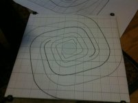
Here is my first cut at a 24 inch x 4 inch deep Cornu with four equal length horns - no bifurcation. In HR I am modeling it as one horn, and in practice, the single horn would be divided into 4 equal horns and rolled up. Note that the channels are now getting very close together in spacing and the 3/16 in thick foam core channels thickness will have to be accounted for. Alternatively, the critical early parts where the dimensions are narrow can be constructed with perhaps thin model building plywood (1/16 in thick birch). The 4 horns each have their own throat starting at the driver chamber. The horns were designed by modifying the Cornu bifurcation divider channel and extending it all the way back to the chamber. Some of the passages were adjusted so that the flow in all 4 channels has the same cross sectional area (see photo of plan drawing). The horn was modeled using a linear cone from the throat to the point where the curved mouth transition is. From there it becomes and exponential horn. I am using the T/S parameters for the Dayton RS100 which has a substantial xmax. The predicted xmax at 52 Hz is still < 1.5 mm. The lower frequency peak is centered at 61 Hz, with the highly amplified mid-bass peaks at 127, 204, and 288 Hz.
The final amplitude of these peaks will have to be adjusted with stuffing placed along the throat to probably about the first third of the horn may work to soften up these peaks. This is something that would be very helpful to build with a foam core back with access "windows" cut out of the back plate for adjustment of the stuffing. The windows can be sealed temporarily with a cover of foam core and plumbers' putty. Then a measurement would be made. Once adjustment provides a good result , the windows can be permanently sealed with the foam core cutouts and hot melt glue. I will use a gram scale to weigh the stuffing and estimate how long it is stretched out so that the stuffing results can be reproduced.
This is my first HornResp attempt, any feedback as to what I can try to improve the horn output would be appreciated. I have also done a similar sim at the 28 inch size with a TB W4-1337SDF with similar, albeit lower freq and higher SPL results. One thing that is interesting is that the depth controls the cross sectional area and volume of the horn, so if you make it too deep, you may have too much bass that you cannot control. It may actually be preferable to make the horn shallower than as calculated based on Sd matching the throat considerations alone. If someone would like to attempt modeling this horn in MJK's Mathcad sheets as a collaboration that would be great - it will allow for adjustment of stuffing before actually building. The HR dimensions are in the pdf file if you are interested in trying this yourself.
Thanks.
Attachments

Last edited:
I'm making a 24" cornu.Chaz,
Good luck with getting the channels glued. What size cornu were you making? The driver you ordered looks like it should work well - looks nice too.
Happy holidays.
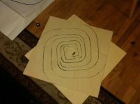
Yesterday I got the design printed, then I copied the pattern onto the baffle with a heavy marker. Images below. My drivers aren't coming until the 3rd so I have some time to get around to gluing. I also bought some polyfil to stuff the chamber and the first third of the horns. Since I'm planning to glue right up, I will only have one chance at horn stuffing; should I err on the side of too much than too little?
Attachments
Chaz,
Great that you are warming up your glue gun now! You might try gluing a string to wad of stuffing and leave string hanging out to adjust or remove. Might need to put stuffing in cheesecloth sack to pull out. Good luck!
Great that you are warming up your glue gun now! You might try gluing a string to wad of stuffing and leave string hanging out to adjust or remove. Might need to put stuffing in cheesecloth sack to pull out. Good luck!
Cornu as MLTL?
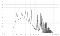
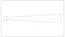
I am testing different horn designs in HornResp and going off-design from original Cornu now. I started with a clean slate and tried various horn profiles that will produce deeper bass extension while having relatively even levels of peaks in the mid-bass region that are equivalent to the main low bass peak. The thinking is if they are even they can be attenuated and smoothed out with stuffing to match the characteristic SPL curve of the driver. The constraint is that it must be rolled up in a spiral and start from a driver chamber. What I ended up with is a linear conical horn with a restricted terminus to both reduce the bass gain, and to pull the bass extension lower - essentially a mass loaded transmission line. This design can be made without curves, and in fact I think use of straight sections only will provide excellent filtering of the HF resonances that the horn produces. My fear is that due to the abrupt terminus with a restriction, the way the sound exits the edges of the cornu and fills the room may be compromised - it may not have the magical wide image as a result.
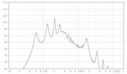
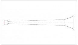
The simulation assumed a 4.5 x 4.5 in x 4 in deep driver chamber with 4 paths leading out starting with a 0.4 in throat (each) to a 6.34 in mouth that has a restrictor plate capping it to allow only a 0.5 in wide x 4 in deep exit vent (each). The overall size of the horn rolled up is about 31 in x 31 in x 4 in deep. Quite a bit bigger than the original cornu, and this is only for a smallish 4 in driver (Daytion RS100).
Attached are the schematic diagram of the HR design and SPL simulation. Please let me know your thoughts on this approach. All wrong and ruins magic of the curved bell mouths?
I am testing different horn designs in HornResp and going off-design from original Cornu now. I started with a clean slate and tried various horn profiles that will produce deeper bass extension while having relatively even levels of peaks in the mid-bass region that are equivalent to the main low bass peak. The thinking is if they are even they can be attenuated and smoothed out with stuffing to match the characteristic SPL curve of the driver. The constraint is that it must be rolled up in a spiral and start from a driver chamber. What I ended up with is a linear conical horn with a restricted terminus to both reduce the bass gain, and to pull the bass extension lower - essentially a mass loaded transmission line. This design can be made without curves, and in fact I think use of straight sections only will provide excellent filtering of the HF resonances that the horn produces. My fear is that due to the abrupt terminus with a restriction, the way the sound exits the edges of the cornu and fills the room may be compromised - it may not have the magical wide image as a result.
The simulation assumed a 4.5 x 4.5 in x 4 in deep driver chamber with 4 paths leading out starting with a 0.4 in throat (each) to a 6.34 in mouth that has a restrictor plate capping it to allow only a 0.5 in wide x 4 in deep exit vent (each). The overall size of the horn rolled up is about 31 in x 31 in x 4 in deep. Quite a bit bigger than the original cornu, and this is only for a smallish 4 in driver (Daytion RS100).
Attached are the schematic diagram of the HR design and SPL simulation. Please let me know your thoughts on this approach. All wrong and ruins magic of the curved bell mouths?
Attachments
Last edited:

wauw...i didn't had any plans on building something but there where plans to build a Cornu spiral and i wanted to build with the Visaton FRS8-8! and possibly with a different material them wood..
So it comes together now.
I wonder if and how it went at Switters with the FRS8 and what dimensions do you have. I don't know why but i had these measurements on a piece of paper:
42*42*6 centimeters that is...
So it comes together now.
I wonder if and how it went at Switters with the FRS8 and what dimensions do you have. I don't know why but i had these measurements on a piece of paper:
42*42*6 centimeters that is...
Xerxes,
If you have the FRS8 already, then use them. I have used the smaller FRS5 in a 35.5 cm x 35.5 cm x 5 cm deep cornu and it works great. I think the 42 cm size is a bit small, try 48 to 60 cm. Adjust the depth to have throat area (both from driver chamber) to equal Sd of driver. If you haven't bought thr FRS8's yet, I would highly recommend getting the Vifa TC9FD, it is about same size, costs $2 more but is probably superior in performance for Cornu. If going with Vifa make it from 50 cm to 61 cm and about 9 cm deep. It can work as shallow as 6 cm deep but you will have better bass with 9 cm.
Good luck and welcome on board. There is a lot of how to build info on foam core thread.
I just asked this question over in the other thread. 🙂 So for the 50 cm box, you recommend the Vifa TC9FD with an inside horn depth of 9 cm. What shape? Is the original good or what about the true spiral that you showed earlier?
Cal,
9 cm should work well, if not opposed to thicker, go as high as 11 cm to match Sd if using Planet10 plan. The more rounded spiral works too, I think Endia has a plan posted somewhere. If you want to make an exact copy of mine, I can photograph the plan as straight as possible and post image. It has sharp corners inside and curves on outside with a 1.1 in wide throat for 2.38 in deep channel.
9 cm should work well, if not opposed to thicker, go as high as 11 cm to match Sd if using Planet10 plan. The more rounded spiral works too, I think Endia has a plan posted somewhere. If you want to make an exact copy of mine, I can photograph the plan as straight as possible and post image. It has sharp corners inside and curves on outside with a 1.1 in wide throat for 2.38 in deep channel.
Ah thanks. I already have the frs8 lying around so I will go with them. You say adjust the depth etc. I must admit I understand anything about these measurements (I really tried..)
My question would be , if I go with 50 x 50 cm what would the depth of the speaker?
My question would be , if I go with 50 x 50 cm what would the depth of the speaker?
Xerxes,
I can't find published Sd for this driver but from photograph, it appears that apex of the surround is same dia as magnet which is 6 cm. Based on this assumption, a speaker depth anywhere from 8.5 to 9 cm should work for a 50 cm x 50 cm cabinet.
I can't find published Sd for this driver but from photograph, it appears that apex of the surround is same dia as magnet which is 6 cm. Based on this assumption, a speaker depth anywhere from 8.5 to 9 cm should work for a 50 cm x 50 cm cabinet.
Ah thanks, I will go with 9cm I like round numbers....I like it already! Tomorrow I will sort out where to score my board, I can't wait.
essentially a mass loaded transmission line
Mass-Loaded Voigt. You can reduce the ripple by tapping the driver in part way down the line (Hoe you would do that phyisically is a different challenge.
dave
Dave, you happen to have some small drivers you might want to send my way for my brother's project? Contact me email or PM and we can discuss.
Ta.
Ta.
- Home
- Loudspeakers
- Full Range
- Ever think of building a Cornu Spiral horn? Now you can!