Transformer source resistance for full-wave has to just use the secondary half winding resistance as that is the winding carrying the secondary current when its diode conducts. But of course - can't find a clarification when you need one.
I think some of the valve diode datasheets also spell out the equation and definition of parameters.
I think some of the valve diode datasheets also spell out the equation and definition of parameters.
From a theoretical physics point I follow your thoughts....this is more a question I guess how the software is programmed and expects which input...
I believe there has been a question what I meant with "Q". As an RC is a 6db and a LC a 12db filter it has also a Q (i guess):
http://www.diyaudio.com/forums/mult...ifference-whats-your-favorite.html#post486754
for better comparison to Rob's manual and curves:
With Butterworth equal Q of approx. 0.7...which gives the fastest raise without overswing to the target amplitude (and staying there calm).
I would have assume that this is something I want in a PSU (but maybe wrong assumption, not sure how important this really is incomparison to other parameter like energy stored...example: a CLCLC with significant L's is much harder to get to a Q=0.7 than a CLCRC. In the first example the second choke is resonating on top of the first one while in the second example the R in the RC is dampening even the one resonance of the first choke....
...all great theory....BUT in practise the second choke brings down ripple(if DCR is the same), stores addionally energy etc...I guess one has to listen to both setups)
______________________
A bit different question: Can you remind me what is a good rule of thumb how much of a step change in current would be a realistic scenario, let's say in a typical El34-pp-ul amp which runs maybe up to 15w in class A and than up to 40w in class ab ? That is for sure much more than just 10% greater current than normal bias of the power pentodes.
It will be interesting to see how important it is to isolate the driver stage from the power stage...or how much dual mono is worth...
I believe there has been a question what I meant with "Q". As an RC is a 6db and a LC a 12db filter it has also a Q (i guess):
http://www.diyaudio.com/forums/mult...ifference-whats-your-favorite.html#post486754
for better comparison to Rob's manual and curves:
An externally hosted image should be here but it was not working when we last tested it.
With Butterworth equal Q of approx. 0.7...which gives the fastest raise without overswing to the target amplitude (and staying there calm).
I would have assume that this is something I want in a PSU (but maybe wrong assumption, not sure how important this really is incomparison to other parameter like energy stored...example: a CLCLC with significant L's is much harder to get to a Q=0.7 than a CLCRC. In the first example the second choke is resonating on top of the first one while in the second example the R in the RC is dampening even the one resonance of the first choke....
...all great theory....BUT in practise the second choke brings down ripple(if DCR is the same), stores addionally energy etc...I guess one has to listen to both setups)
______________________
A bit different question: Can you remind me what is a good rule of thumb how much of a step change in current would be a realistic scenario, let's say in a typical El34-pp-ul amp which runs maybe up to 15w in class A and than up to 40w in class ab ? That is for sure much more than just 10% greater current than normal bias of the power pentodes.
It will be interesting to see how important it is to isolate the driver stage from the power stage...or how much dual mono is worth...
Last edited:
Ian, that is a great tutorial, I aaked myself always how to ise the step response....now I know it...
Are you sure on the right DCR of the secondary When using Fullwave with CT ??
I most often use transformers without center taps, but use the full-wave setting with using damper diodes in PSU II.
This is because in reality, I use a combination of damper diodes and silicon diodes in a graetz bridge (virtual center-tap). For this simulation I use the DCR of the full secondary. It is surprisingly close to real-life measurements.
I also have a few center tapped transformers and they also worked very well when using the full secondary DCR.
Even further, I have some transformers with ZERO data... some are old but still good.
In the tutorial I might not have been so clear on all you really need - you need your mains voltage and the DCR of the primary. In worst-case, you can simply measure the static resistance of the primary with any reasonably decent DMM - but not a bench meter.
Meanwhile I found a thread in audioasylum where a user answer this question like this:
"
With any center tapped transformer, you only consider the end ( either end ) of the high voltage winding, to the center tap, as the PSUD2 entry voltage.
For entering DCR, determine first, the primary's DCR and second, the HV secondary's DCR ( and with a center tap, the end-to-center-tap DCR ) and then use this guide :
When you work with Duncan amps PSU Designer II, please use the formula for
Rtransformer:
Rtr. = Rsec. + (n x n x Rprim.)
Rsec. = DC Resistance secondary [Ohm], measured between (0V - high volt) of one 'leg'.
n = step-up ratio (= voltage secondary / voltage primary)
Rprim. = DC Resistance primary [Ohm]
This is the transformer resistance as it's 'seen' by the rectifier
tube.
"
As a matter of fact, I tried to simulate how to use my Lundahl transformer which has two 0-250V withh 100ohm each in a away where I can switch (with a switch actually) from 250-0-250 in FW to 250-0. Purpose is to understand if you can hear a difference between FW (and a windings resistance of 100/200ohm, pure tube rectification) and Bridge(with two silicon diodes in hybrid-mode and two parallel windings, so 50Ohm).
When I am using PSUD to simulate both, I get the exact same power-on behavior (with a little different voltage-levels, but same Q) when I use 50Ohm for the bridge and 100Ohm for FW. So, I thought 0-Hv resistance isthe right value in a FW-Rectifier for PSUD ?? When plugging in 200ohm, the whole Q/start-up behavior changes dramatically and I would have to add restance to the bridge rectifiers to make them slower to compare the effect of the concepts and now just the Q of the Psu.
I don't like commenting on audioasylum, but you will notice that many of the regulars here don't post there. If you look at Duncan amps software in detail you will see that it appears to do much of what is described.
Adding serial resistance to the secondaries will definitely reduce transformer ringing, overshoot, etc. It will also lower your B+ and you will notice that your power supply might not respond as quickly to sudden changes in current.
Ian
Transformer source resistance for full-wave has to just use the secondary half winding resistance as that is the winding carrying the secondary current when its diode conducts. But of course - can't find a clarification when you need one.
I think some of the valve diode datasheets also spell out the equation and definition of parameters.
This could be right! The only center tapped transformer I personally used in PSU II was a Hammond, and the datasheet were very detailed. But Hammond secondaries have ridiculously low DCR so it might not have made much of a difference if you entered 50 ohm or 25 ohm...
For the transformers I normally use, there is no true center tap - I use a Graetz bridge arrangement with silicon diodes to create a center tap. For those simulations I use the resistance of the full winding and measured values match simulations very well.
Ian
Sorry, no way to edit my last post.... I use silicon diodes to create a virtual center tap. I however simulate using damper diodes in full-wave configuration.
This has always simulated very well for me.
Ian
This has always simulated very well for me.
Ian
When I am using PSUD to simulate both, I get the exact same power-on behavior (with a little different voltage-levels, but same Q) when I use 50Ohm for the bridge and 100Ohm for FW. So, I thought 0-Hv resistance isthe right value in a FW-Rectifier for PSUD ??
This is a lot easier and simpler if you use a proper circuit simulator like Tina. Then you can tailor everything. Just sayin'.
I also use LTSpice.... its probably more work to simulate a power supply than with tina though.
Last edited:
Good hint...did not now anything about Tina so far...what would be a good starting point / tutorial to get into it ?
When I am using PSUD to simulate both, I get the exact same power-on behavior (with a little different voltage-levels, but same Q) when I use 50Ohm for the bridge and 100Ohm for FW. So, I thought 0-Hv resistance isthe right value in a FW-Rectifier for PSUD ?? When plugging in 200ohm, the whole Q/start-up behavior changes dramatically and I would have to add restance to the bridge rectifiers to make them slower to compare the effect of the concepts and now just the Q of the Psu.
I don't pay so much attention to power-on since it just doesn't give you much information about how the power supply works under load. It might be useful to show you if you have some issues with ringing, but you will see that anyway if you start adjusting stepped load values to simulate changes in current draw.
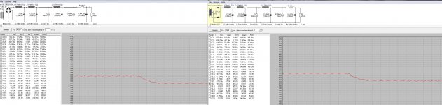
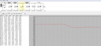
To answer the question as cleanly as possible wrt full wave vs. bridge, I did a simple simulation using silicon diodes. Since they have such low DCR. If I used damper diodes, I would have to factor in the Ri of each tube.. etc. I Don't use silicon diodes this way btw - I use damper diodes in my builds - this is just a test to see how PSU II behaves.
In the first screen shot, I just changed from bridge to full wave with no change in secondary impedance. The voltages are nearly identical - a bit lower for the bridge (I guess those silicon diodes do have a tiny bit of DCR after all).
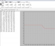
In the second screen shot, I cut the secondary impedance in half. Look at how the B+ shoots up now (which is incorrect for that supply).
These pictures should tell you everything you need to know.
Just an aside, but that supply settles after a 30mA current change, without ringing or much overshoot in 20ms (even when you use 6ax4-GT) in simulations - which is not bad. Try to beat it if you can. Of course today we have the possibility of fully regulated solid state supplies which can do even better. Alas, those supplies do not have glass bottle that emit heat and a pretty spectrum of photons. My wife prefers the kind that glow.
Attachments
Last edited:
Here is what I used in that supply.
It performs just like simulated. The power transformer and chokes are from Thomas Mayer. All caps are film. Nice Q factor? 😉
It performs just like simulated. The power transformer and chokes are from Thomas Mayer. All caps are film. Nice Q factor? 😉
Attachments
Last edited:
Well, my scenario is the other way round: two windings 0-250 with each 100ohm. So, in bridge mode: Parallel windings with 100/2 Ohm, so 50Ohm. In Fw, windings connected in series with each other : 100 ohm measured from 0-250 or 200 Ohm measured from 200-0-200.
So you would compare in your example to debug the software 61 ohm vs. 122ohm as option A.) and 61 ohm vs. 244 Ohm as option B.).... and not 61 vs 31. May I ask you for the favour to drop these values in ?
So you would compare in your example to debug the software 61 ohm vs. 122ohm as option A.) and 61 ohm vs. 244 Ohm as option B.).... and not 61 vs 31. May I ask you for the favour to drop these values in ?
I used 61 ohms for bridge and full wave. Results near identical.
Then I used 30.5 ohms for full wave (as if the value was for half the winding - just to the CT). Resulting B+ shoots up to incorrect levels.
You can use different resistor values if you want but the behaviour will not change,
Then I used 30.5 ohms for full wave (as if the value was for half the winding - just to the CT). Resulting B+ shoots up to incorrect levels.
You can use different resistor values if you want but the behaviour will not change,
Using Cree SiC to simulate...
B+ for 61 ohm full wave = 456.2V
B+ for 122 ohm full wave = 437.1V
B+ for 244 ohm full wave = 400.7V
B+ for 61 ohm Bridge = 454.7V
B+ for 122 ohm Bridge = 435.5V
B+ for 244 ohm Bridge = 399.3V
See?
B+ for 61 ohm full wave = 456.2V
B+ for 122 ohm full wave = 437.1V
B+ for 244 ohm full wave = 400.7V
B+ for 61 ohm Bridge = 454.7V
B+ for 122 ohm Bridge = 435.5V
B+ for 244 ohm Bridge = 399.3V
See?
Well, my scenario is the other way round: two windings 0-250 with each 100ohm. So, in bridge mode: Parallel windings with 100/2 Ohm, so 50Ohm. In Fw, windings connected in series with each other : 100 ohm measured from 0-250 or 200 Ohm measured from 200-0-200.
So for this scenario:
For bridge (ie. no center tap) you have two options:
a. Use your windings in series (get the phase correct!) to get 500V and 200 ohm DCR. You will need to cut the current handling in half if you do this though. Ugh... no fun.
b. Use the windings in parallel (again, get the phase correct!) to get 250V, and have only 50 ohms DCR.
For full wave: You can use each winding as designed, tie the center tap and use 250V and 100 ohms. I am now thinking this because for each cycle, you have 250V and 100 ohm DCR in the path.
Sorry if this adds to your confusion. Its good to get this straight though (at least for me - I haven't used a CT transformer in quite a while).
What is the manufacturer? Any data available?
Last edited:
Sure: http://www.lundahl.se/wp-content/uploads/datasheets/1683.pdf
...And yes, the voltage is a bit different between bridge and fw....but was there not something around efficiency of the rectifying concepts with FW a little less efficient ? I wanted to compare apples with apples and on the Lundhl trnsformer we have a nice example: With the same core I can get either a FW winding with less current capability and more resistance OR a bridge winding scenario with double the current and half the resistance of the sec. Now, the Bridge needs silicon plus tune....which one Sounds better ? I will try both and will report.
...And yes, the voltage is a bit different between bridge and fw....but was there not something around efficiency of the rectifying concepts with FW a little less efficient ? I wanted to compare apples with apples and on the Lundhl trnsformer we have a nice example: With the same core I can get either a FW winding with less current capability and more resistance OR a bridge winding scenario with double the current and half the resistance of the sec. Now, the Bridge needs silicon plus tune....which one Sounds better ? I will try both and will report.
Last edited:
Hi Blitz
I think one of the lowest rectifier DCR's will be with a voltage doubler btw. Just like Marantz once did 😉
Look at my simulations again and try to do better.
Ian
I think one of the lowest rectifier DCR's will be with a voltage doubler btw. Just like Marantz once did 😉
Look at my simulations again and try to do better.
Ian
Ok, so I checked this now.
Example in Duncan amps: Universal Transformer with 2x 115V primary windings, each with 4.3 ohm static resistance, and two 350VAC secondary windings, each with 72 ohm static resistance.
Primary resistance for windings in parallel (ie. 115V mains) will be 2.15 ohms.
Primary resistance for windings in series (ie. 230V mains) will be 8.6 ohms.
If you are using the windings for a full-wave rectifier, the static resistance to enter is the sum of both secondary windings =144 ohms and the voltage is 350VAC (ie. two leads of opposite phase go to ground, the two other leads are each 350V opposite phase).
If you are using a bridge, you can use the secondary windings in parallel, the static resistance is half of both secondary windings = 36 ohms. HT is still 350VAC.
You could do a bridge with both secondary windings in series. To do this, basically you float the center tap. The static resistance would the sum of both secondary windings (ie. 144 ohms). The HT will be 700VAC but the power handling capacity will be cut in half.
Getting these static resistance values correct is useful, since you can use Duncan amps software to calculate the correct secondary impedance for your simulation.
When using Duncan ohms software, you can edit the transformer properties, click the ... button after Source Res and enter all relevant values to get the secondary impedance.
The only thing you will need in addition to the correct primary and secondary winding resistances will be the off-load voltage.
Ian
Last edited:
Ian, how did you verify the full bridge secondary winding resistance, setting, which is ambiguous and could be 72 or 144 ohm.
I had manufacturer data on the transformer's static resistances, off-load voltages, did measurements and compared them to simulations.
Of course, I only did this with one transformer from one manufacturer. But the measurements were pretty darn close to simulations based on the manufacturer data..
Of course, I only did this with one transformer from one manufacturer. But the measurements were pretty darn close to simulations based on the manufacturer data..
Last edited:
Calculated impedance values can be significantly different depending on which static resistance values are used.
Look at it this way - if there is a ground reference at the center tap, the impedance between the HT+ leads is not different than if there is no ground reference. The only difference is power handling.
If the windings are however in parallel then the HT+ is also the same as above, as is power handling capability. However the serial resistance is half.
In the example above, when each winding is 72 ohms static resistance, for series resistance of 144 ohms (full wave using center tap ground or bridge at double HT and half the power) PSU II gave an estimated impedance of 164.258 Ohms
However if the windings are in parallel, the static resistance was 36 ohms and the estimated impedance was 56.258 ohms. Both sims compared well to measured. "Alternative" values did not.
Ian
Last edited:
- Status
- Not open for further replies.
- Home
- Amplifiers
- Power Supplies
- Estimating load for Duncan Amps PSU tool HOWTO?