In trying to design a PSU, I am not sure how to calc the estimated load, and the current requirement for the transformer. I would like to use some relatively high plate current tubes (starting to try and design some things, but want to use something like a 6W6, 6AS7, etc). This thread recommends putting in a current tap for the estimated current draw of each tube: http://www.diyaudio.com/forums/tubes-valves/196009-duncan-amps-psu-designer-ii-help.html but I want B+ to be constant across the circuit. For illustration, let's say I have four tubes, two that draw max 50mA and two that draw max 5mA. Can I just put in one current tap for 110mA? May I use a 110mA transformer and then just plug in capacitor and resistor values that meet my B+ and frequency response requirements? Or do I need to use a 250mA transformer which is the RMS value for I(T1) on the PSUD, or 350mA which is on the graphical display. I can't seem to find the answer to this anywhere. For this illustration I have a 250v transformer, the values come up with about 250v B+
Attachments
If you want 250v across the power section and preamp sections then you would still use more CR filters for you preamp nodes. When you do the simulation it will give you a more accurate view of ripple for your preamp section. I believe you right click and insert on your diagram, just use small R values in the CR filters. With each section you can add a current tap for the specific current draw for that node.
For current draw more information is needed. What class amp is this going to be?
For current draw more information is needed. What class amp is this going to be?
Last edited:
I am not familiar with the valves you mentioned, and I hope I am not misunderstanding your question, but usually we have a sequence of dropper resistors and smoothing capacitors as we go 'back' towards the input stage. This is to provide reduced ripple on the supply to the more sensitive stages. Equally important, it 'decouples' the stages to avoid 'motor-boating' instability. The B+ then inevitable drops as we go back towards the input.
Hope this helps, and my apologies if I have misunderstood what you are trying to do.
Hope this helps, and my apologies if I have misunderstood what you are trying to do.
Last edited:
Hah, that is part of my learning curve. I am starting out with simple two stage triode (or triode strapped pentodes) preamp circuits. The triodes will be in separate bottles. (Proposing a high mu triode and then a low mu triode strapped pentode for each channel. ) I am assuming class A. The first stage current draw is a few mA, in my example 5mA. The second stage is going to be around 20-30mA, so I picked 50mA. So do I put a constant current of 110mA for the PSUd? or two taps, one for the pair of triode strapped pentodes and one for the triodes? And then how to I calc the current req't for the transformer. If I'm reading the PSU designer correctly, I'd need a transformer rated at 250mA. The main question is 1. how to determine the load for the PSU (i.e. what and where to put the constant current) 2. how to determine the current rating of the transformer I can see the need for additional filtering, but if I add another RC stage, What I am want to know is how to estimate the load for the power supply, and the current rating I will need for the transformer. I do not know how to put a resistive load or a constant current for the designer. E.g. if I have two tubes that draw max current of 50mA each, do I put a current sump of 100mA for the calculator? And if so, what is the current rating of the transformer
So do I put a constant current of 110mA for the PSUd? or two taps, one for the pair of triode strapped pentodes and one for the triodes?
The latter, two taps.
And then how to I calc the current req't for the transformer.
Well from what I can extrapolate from the information given without a schematic I assume the current will be somewhat constant in your circuit. I am not really familiar with the software but I am assuming that the 250mA for T1 is for the primary, 110mA at 250v (secondary) or 220mA 120v (primary). Kirchoffs law?
So if you plan on pulling 110mA then that is the minimum rating of a power transformer you need.
how to determine the load for the PSU (i.e. what and where to put the constant current)
The load is 110mA, you put the current taps on each node. So for you there would most likely be two, 100mA for the low mu triode strapped pentode, and 10mA for the high mu triode.
how to determine the current rating of the transformer I can see the need for additional filtering, but if I add another RC stage, What I am want to know is how to estimate the load for the power supply, and the current rating I will need for the transformer.
You don't have grossly huge capacitors in your power supply so they won't have a ridiculous inrush current, 110mA is your secondary load, primary might be more due to other secondary loads like heater taps.
I do not know how to put a resistive load or a constant current for the designer. E.g. if I have two tubes that draw max current of 50mA each, do I put a current sump of 100mA for the calculator? And if so, what is the current rating of the transformer
If the two tubes drawing 50mA are on the same node then yes put the sum of both those tube as the current source. The combined sum of current sources will be your rating spec.
I hope for your sake I am understanding your questions correctly and/or somebody else will chime in and give you better advice.
Thanks!!
OK, I think I see it.
So if I am understanding correctly:
I have four tubes. From the plate curves I've drawn, V1 and V2 will each draw 5mA, V3 and V4 will each draw 50mA. Total equals 110mA. I draw a PSUd with two B+ nodes B1 with a 100mA sump and B2 10mA. So far so good. I connect the low mu tubes to B1 and the high mu to B2.
I need a transformer secondary rated at 110mA.
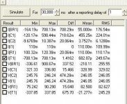
What was throwing me off is the simulator was saying I(T1) is about 150mA, which I now see is what the PSU itself is drawing from the mains.
OK, I think I see it.
So if I am understanding correctly:
I have four tubes. From the plate curves I've drawn, V1 and V2 will each draw 5mA, V3 and V4 will each draw 50mA. Total equals 110mA. I draw a PSUd with two B+ nodes B1 with a 100mA sump and B2 10mA. So far so good. I connect the low mu tubes to B1 and the high mu to B2.
I need a transformer secondary rated at 110mA.
What was throwing me off is the simulator was saying I(T1) is about 150mA, which I now see is what the PSU itself is drawing from the mains.
No. DC current draw of 110mA does not equate to a transformer secondary AC rating of 110mA (unless you are using a choke input supply). The transformer must be rated for the RMS current, which PSUD2 will give you. This will be rather greater than the DC current.
You can relax this requirement for a Class B amp which will be amplifying real music, as it will have a low duty cycle. For Class A or highly-compressed music you have to have a bigger transformer.
You can relax this requirement for a Class B amp which will be amplifying real music, as it will have a low duty cycle. For Class A or highly-compressed music you have to have a bigger transformer.
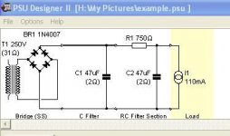
250 mA is a safe rating to use. The transformer will likely have more series resistance than 31 Ohms and some leakage inductance, which will result in a bit less RMS current. So you MIGHT get by with a 200 mA transformer. But the current carried by the transformer is always more than the DC current when you use a full-wave bridge with cap input. RMS current is the value you need to look at, as that's the value used for a transformer rating.
When the full-wave center-tap circuit is used, each half carries current half the time and the load current is close to the value of RMS current in the winding.
When the full-wave center-tap circuit is used, each half carries current half the time and the load current is close to the value of RMS current in the winding.
As far as the transformer is concerned, yes you can put the current source where you have it now. Ultimately it is sucking 110mA from the raw power supply, just like your imaginary amp circuit. But if you were modelling multiple filter stages then you would put your current taps in the corresponding places where the valves would be placed in reality.1. how to determine the load for the PSU (i.e. what and where to put the constant current)
As already pointed out, it must handle the RMS current, or about 250mA in your example. However, your transformer winding resistance is rather unrealistically low (31 ohms). I would expect about 100 ohms. This will reduce the RMS current. In reality you should find the RMS current is about 1.5 to 1.7 times the average DC load current. For your 110mA example, I would use a 170mA transformer as a minimum.2. how to determine the current rating of the transformer
But how do I know how much transformer resistance to use? Well it's a bit of iterative guess work. You're currently looking at a 250V, 250mA transformer right now, or 62.5VA. A transformer of that size will most likely have a regulation figure of about 8%. In other words, it will deliver about 270Vac off load, falling to 250V when the full 250mA is demanded. That's a source resistance of 20V/0.25A = 80 ohms. But such a transformer would be overkill; in reality a 200mA transformer would be more than enough in this application, and would probably have a source resistance of at least 100 ohms. I'd use that figure to begin with at least.
For a Class A amp the load current is substantially constant, so either a resistor or current source works equally well. I prefer to use resistors as they are somewhat more representative of how a real amp works (i.e. if the supply voltage rises, the load current will rise too).I do not know how to put a resistive load or a constant current for the designer.
Yes.E.g. if I have two tubes that draw max current of 50mA each, do I put a current sump of 100mA for the calculator?
Last edited:
I can't edit my previous post where I gave some bad advice on RMS AC current. As pointed out buy a few others the rating of the transformer will be slightly more than the 110mA load. Maybe I can get a mod to edit the misinformation.
Thanks and sorry for the bad advice, lack of sleep is getting to me.
Thanks and sorry for the bad advice, lack of sleep is getting to me.
@DF96/Merlinb: Thanks once again. I have put everything to use here (except I'll need to guesstimate the actual transformer resistance) and I think I have it figured out now. Based on a rough estimate and the tentative real circuit, I should be good to go. Using max current on a load line, I'm still OK. @'bird, odd thing about the editing, homerecording.com is a few days, groupdiy, is basically foreverer.
PSUD will figure the transformer impedance for you. When you are at the 'Edit transformer properties' window, click the '...' button next to 'Value' (but not the one by 'Source res'). Enter the transformer's voltage and current rating, then click on the 'Regulation' input box (but don't change it) so the calculator will update. You can easily find voltage/current ratings on manufacturer pages.
PSUD will figure the transformer impedance for you. When you are at the 'Edit transformer properties' window, click the '...' button next to 'Value' (but not the one by 'Source res'). Enter the transformer's voltage and current rating, then click on the 'Regulation' input box (but don't change it) so the calculator will update. You can easily find voltage/current ratings on manufacturer pages.
Thanks. It is a very handy program now that I know how to use it....
I have been readingthroighthis including the great manual from dhtrob...and havesome more questions:
- When Rob talks about his 721 Ohm secondary winding resistance for a CT transformer: Is this for the total secondary or measured from CT, so only each half ? I assume it is forthe total secomdary, correct ?
- If I understand Rob's manual right, we want not just low ripple, but a q of 0.7, so a fast raise in voltage without overshooting. He is using the power-on behaviour to determine this, correct ?
- How would you analysis the regulation behaviour of a PSU, so lets assume a typical El-34-UL-PP amp. You have a bias of 200mA at 350V for the Output tubes and it runs in Class A/B obviously. So, how would you simulate the current need/voltage change when it goes into class B heavily ? I saw the function step response, but cant see a meaningfu result as it only shows the higher current result...
-How could you simulate the isolation effect of channel seperation or isolation driver va. output stage ?
Thx a lot
Some transformer manufacturers provide useful specs which you can enter directly into PSU II.
Experts here will no doubt find immense fault in this quick-and dirty tutorial that I put together for someone else. Such is life.
Look chiefly at steps 1-10 and ignore anything that might resemble my opinion.
Best regards
Ian
Experts here will no doubt find immense fault in this quick-and dirty tutorial that I put together for someone else. Such is life.
Look chiefly at steps 1-10 and ignore anything that might resemble my opinion.
Best regards
Ian
Attachments
When Rob talks about his 721 Ohm secondary winding resistance for a CT transformer: Is this for the total secondary or measured from CT, so only each half ? I assume it is forthe total secomdary, correct ?
This is the DCR of the whole secondary. Many transformer manufacturers have this data available, which makes using PSU II easy. Check out Hammond or Lundahl for their excellent specification sheets.
- If I understand Rob's manual right, we want not just low ripple, but a q of 0.7, so a fast raise in voltage without overshooting. He is using the power-on behaviour to determine this, correct ?
This is indeed what he does.
- How would you analysis the regulation behaviour of a PSU, so lets assume a typical El-34-UL-PP amp. You have a bias of 200mA at 350V for the Output tubes and it runs in Class A/B obviously. So, how would you simulate the current need/voltage change when it goes into class B heavily ? I saw the function step response, but cant see a meaningfu result as it only shows the higher current result...
-How could you simulate the isolation effect of channel seperation or isolation driver va. output stage ?
Thx a lot
Check my attachement in the previous post.
Ian
Ian, that is a great tutorial, I aaked myself always how to ise the step response....now I know it...
Are you sure on the right DCR of the secondary When using Fullwave with CT ??
Meanwhile I found a thread in audioasylum where a user answer this question like this:
"
With any center tapped transformer, you only consider the end ( either end ) of the high voltage winding, to the center tap, as the PSUD2 entry voltage.
For entering DCR, determine first, the primary's DCR and second, the HV secondary's DCR ( and with a center tap, the end-to-center-tap DCR ) and then use this guide :
When you work with Duncan amps PSU Designer II, please use the formula for
Rtransformer:
Rtr. = Rsec. + (n x n x Rprim.)
Rsec. = DC Resistance secondary [Ohm], measured between (0V - high volt) of one 'leg'.
n = step-up ratio (= voltage secondary / voltage primary)
Rprim. = DC Resistance primary [Ohm]
This is the transformer resistance as it's 'seen' by the rectifier
tube.
"
As a matter of fact, I tried to simulate how to use my Lundahl transformer which has two 0-250V withh 100ohm each in a away where I can switch (with a switch actually) from 250-0-250 in FW to 250-0. Purpose is to understand if you can hear a difference between FW (and a windings resistance of 100/200ohm, pure tube rectification) and Bridge(with two silicon diodes in hybrid-mode and two parallel windings, so 50Ohm).
When I am using PSUD to simulate both, I get the exact same power-on behavior (with a little different voltage-levels, but same Q) when I use 50Ohm for the bridge and 100Ohm for FW. So, I thought 0-Hv resistance isthe right value in a FW-Rectifier for PSUD ?? When plugging in 200ohm, the whole Q/start-up behavior changes dramatically and I would have to add restance to the bridge rectifiers to make them slower to compare the effect of the concepts and now just the Q of the Psu.
Last edited:
The PSUD2 model for transformer winding resistance includes a contribution from the primary side, so the value to use in each of Blitzs' sims (bridge and full-wave) won't be 50 and 100 ohms, but something like 55 and 105.
It would be great if a poster can insert a screen grab of each sim circuit that is being commenting on, as it is very easy then for others to quickly make up that circuit and make accurate responses.
Blitz, not too sure I appreciate what you mean by 'Q'. If you are using CRC filter then you will just get a simple rise time response - which will be somewhat different for your two circuits as the transformer effective resistance is different.
Be mindful that an output stage does not really act like a constant current sink when you turn on the power supply. A resistance load may be a better approximation, but that also needs appreciation that without any softstart setting, you are assuming a 'hot' start where you have turned off and on the amp with only a short break.
Last edited:
Thanks for your hints...and yes, the 50/100ohm was not the complete and correct value it is more like you said, but I wanted to clarify if 50/100 or actually 50/200 is correct...and the answer is ???
I understood from Ian 50/200, but from the other guy 50/100....you agree to 55/105 if I understand you correct...
Ian, can you please explain your thinking behind r1, r2 and c3 ? I am not sophisticated enough in my thinking yet I guess, my model would stop with the last current sink after the hammond choke.
Interesting idea to build a cap-input voltage wise, but have a very small choke in a choke-input way...I guess you did that not for ripple, but hf-filtering ?
Best Regards
Frank
- Status
- Not open for further replies.
- Home
- Amplifiers
- Power Supplies
- Estimating load for Duncan Amps PSU tool HOWTO?