I think I used one called os.xls, but I can't find it. Here is one called oswg.xls, I may have used it. You should be able to specify throat area, throat angle, oswg angle etc with a graphic you can work off - Gummed up with OS Waveguide spreadsheet and formula.
Hi AllenB,
thank you, I will try tomorrow.
Re-scaling the curve did not work. I will draw DonVK's references in CAD and use a spline to see how that will work.
Kindest regards,
M
thank you, I will try tomorrow.
Re-scaling the curve did not work. I will draw DonVK's references in CAD and use a spline to see how that will work.
Kindest regards,
M
Hi AllenB,
Hi DonVK,
would you have the curve without the red reference lines? If so, I could use the squares to read twice the number of points for a better accuracy. But, perhaps it is not necessary?
Kindest regards,
M
If I delete the red lines then the dimensions will also be removed.
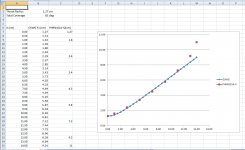
I've compared the vertical PHRN1014 profile to OSWG. I would expect this to be similar to @mabat's ATH where some portion (first 50%) is OSWG then some portion is mouth termination (last 50%). It looks close but it could also be a Quadratic which is close to this curve. You can see the deviation for mouth termination starting at 10cm. As I said, manual measurements have some noise that's why I used FreeCad's B-spline to smooth the curve.
I've included the xcel spreadsheet if you wanted to experiment.
.
Attachments
Last edited:
Hi AllenB,
in my experience, the splines are rather tricky, depending on the end conditions.
Hi DonVK,
thank you for the spreadsheet. I have recalculated using your spreadsheet with 60 deg angle, which yields the same figure as I posted.
I agree with your description of the B52-PHRN-1014 curve vis-a-vis the ATH4.
I have gotten an idea how to determine the curve precisely, but it will have to wait until I visit my friend who has the tools required. In a meanwhile, I will continue with the spline idea and your spreadsheet.
Kindest regards,
M
No problem, and you're welcome.
If you can get a more precise measurement, I would be interested as well. Mine was sufficient for it's purpose 🙂
If you can get a more precise measurement, I would be interested as well. Mine was sufficient for it's purpose 🙂
Hi DonVK,
I am not having much luck with the spline. As I mentioned to AllenB, the spline, especially the throat and mouth portion of the curvature, significantly changes with the selected endpoints. And since minor changes, especially around the throat, have great influence, at least based on my initial attempts with ATH4, I want to get it right.
Kindest regards,
M
What CAD tool are you using?
Hopefully your friend has the special gauges required to accurately measure the throat with mm precision. It's the loft transition between round and approx square that was difficult for me.
Here is another similar shape, the Quadratic throat (pg 8 of the article). https://peaveycommercialaudio.com/w...atic-Throat-Waveguide-by-Charles-E-Hughes.pdf
.
Attachments
Last edited:
Hi DonVK,
I am comfortable with AutioCAD, which I was using for the spline. I also have Solidworks, but I am just learning.
I am not sure, whether we will be able to measure the transition with a great degree of accuracy, furthermore, I am also not certain whether the morphing feature in ATH4 could approximate it correctly.
I am aware of the paper, but as I do not have access to 3D printer, I want to use a ready-made wave-guide, and extend it, something like bwaslo did. I am planning to use foam-board and fiberglass/carbon-fiber because it will make a strong and light structure, as witnessed by aircraft modelers.
Kindest regards,
M
Attachments

Not to pour water on you idea but I think you will waste a lot of time trying to get anything useful for this purpose in Ath directly. You can use the lessons from other waveguides built with it though.I am also not certain whether the morphing feature in ATH4 could approximate it correctly.
The QSC clone already has a mouth transition built into it, to really make the waveguide itself bigger and control directivity lower you would need to undo that transition and make your own further out. This will not be easy and is questionable whether the effort is worth it.
You could extend the mouth to make the waveguide perform better to turn it into a gentle rollback or smoother transition into a baffle. You could do that quite easily with paper or thin mdf templates. What you want is to smooth the transition and have it change as gently as possible.I am planning to use foam-board and fiberglass/carbon-fiber because it will make a strong and light structure, as witnessed by aircraft modelers.
The real benefit in Ath is being able to control that curve from the throat or even into the phase plug. With a ready made waveguide you are already stuck with most of what you have.
bwaslo's isn't quite the same as he is using a stub to transition into a conical section.
Hi fluid,
no worries about pouring water on my idea. In fact, thank you for joining the discussion.
I do not understand your comments, though. If you state that the wave-guide has a transition built in, it logically follows that if one can establish the expansion before the transition and the plane where the transition starts, one can cut the wave-guide at that plane to obtain the "stub", using your terminology. Then, one can use ATH4 to design a new transition with the required mouth dimensions.
I also seem to have difficulty to reconcile your statements. As I understand it, on one hand you are saying that "This will not be easy and is questionable whether the effort is worth it", on the other hand you are saying that :"You could extend the mouth to make the waveguide perform better to turn it into a gentle rollback or smoother transition into a baffle."
Also, in this regard, how can one know that which one is performing better is one does not have two models, one for the original one wave-guide, one for the one with smoother transition to baffle, to ascertain the difference?
Could you please clarify?
Kindest regards,
M
Yes you can.I do not understand your comments, though. If you state that the wave-guide has a transition built in, it logically follows that if one can establish the expansion before the transition and the plane where the transition starts, one can cut the wave-guide at that plane to obtain the "stub", using your terminology.
This is where the difficulty will come in, Ath is not designed to do this. You may get close but there will be a fudge factor and it will not be straightforward. To have it work you need to replicate the guide in Ath as it stands where you would cut it in order to then change the parameters to create an extension. It would make much more sense to me to use the existing contour, extend that based on the extra size you want and create a smoother transition using a CAD program to morph them into 3D. That can then be simulated in ABEC to see what the effect will be.Then, one can use ATH4 to design a new transition with the required mouth dimensions.
I am questioning whether this is a practical way to tackle the problem.I also seem to have difficulty to reconcile your statements. As I understand it, on one hand you are saying that "This will not be easy and is questionable whether the effort is worth it", on the other hand you are saying that :"You could extend the mouth to make the waveguide perform better to turn it into a gentle rollback or smoother transition into a baffle."
Other than a model you would have to measure an original to compare it to the modified one.Also, in this regard, how can one know that which one is performing better is one does not have two models, one for the original one wave-guide, one for the one with smoother transition to baffle, to ascertain the difference?
What do you hope to achieve by modifying the waveguide? That would help to understand the best way to go forward.
Hi fluid,
thank you for your explanation.
I will start with your last question:
I want to make a rectangular 90 deg by 60 deg wave-guide with mouth dimension about 30 in x 21 inch, to be used as a basis for MEH.
You might recall that you and I were discussing the importance of the throat portion of the wave-guide, and since I do no have 3D printing ability, and the wave-guide in question appears to have a well designed throat section, this is, for me, the path of the least resistance.
This is the point that I still cannot understand.
Let us stipulate, for the sake of understanding, that the wave-guide is OS in both vertical and horizontal planes up to a certain axial dimension. (This, in fact appears to be the case form my initial measurements). This dimension is (1) where the original wave-guide would be cut, and (2) from which one can design the rest using the ATH4. From my, albeit initial experiments, this is one manner in which ATH4 works, i.e., one defines an OS expansion and from a certain point introduce the transition.
Note, that the determined dimension for cutting the wave-guide is not a limitation, one can extend it as necessary in ATH4 and then built it into the extension.
Of course, in fact I already have such measurements with the CD I intend to use.
Kindest regards,
M
thank you for your explanation.
I will start with your last question:
What do you hope to achieve by modifying the waveguide?
I want to make a rectangular 90 deg by 60 deg wave-guide with mouth dimension about 30 in x 21 inch, to be used as a basis for MEH.
You might recall that you and I were discussing the importance of the throat portion of the wave-guide, and since I do no have 3D printing ability, and the wave-guide in question appears to have a well designed throat section, this is, for me, the path of the least resistance.
This is where the difficulty will come in, Ath is not designed to do this. You may get close but there will be a fudge factor and it will not be straightforward. To have it work you need to replicate the guide in Ath as it stands where you would cut it in order to then change the parameters to create an extension.
This is the point that I still cannot understand.
Let us stipulate, for the sake of understanding, that the wave-guide is OS in both vertical and horizontal planes up to a certain axial dimension. (This, in fact appears to be the case form my initial measurements). This dimension is (1) where the original wave-guide would be cut, and (2) from which one can design the rest using the ATH4. From my, albeit initial experiments, this is one manner in which ATH4 works, i.e., one defines an OS expansion and from a certain point introduce the transition.
Note, that the determined dimension for cutting the wave-guide is not a limitation, one can extend it as necessary in ATH4 and then built it into the extension.
Other than a model you would have to measure an original to compare it to the modified one.
Of course, in fact I already have such measurements with the CD I intend to use.
Kindest regards,
M
I've never had a problem. I use the other spreadsheet which marks the start point based on the CD throat angle, then import and scale a screenshot of it. Then apply the correct end tangents using construction lines, and then fit a spline. Three points.I am not having much luck with the spline.
Attachments
I want to make a rectangular 90 deg by 60 deg wave-guide with mouth dimension about 30 in x 21 inch, to be used as a basis for MEH.
This is quite big I wonder if foamboard and fibreglass will work out. mark100 had trouble using this method of construction putting extra flares on one of his builds.
Another thing to consider is the other drivers you intend to use and how they will be mounted. With this horn as a base 1" CD's are not going to go low enough to avoid some sort of midrange driver. Where that needs to be mounted along the length might have a big impact on where you want to cut the B52.
When I look at the spreadsheet the B52 does not look pure OS to me, trying to match that in Ath will be tricky and if you are off by more than a mm joining them correctly could be difficult.This is the point that I still cannot understand.
Let us stipulate, for the sake of understanding, that the wave-guide is OS in both vertical and horizontal planes up to a certain axial dimension. (This, in fact appears to be the case form my initial measurements). This dimension is (1) where the original wave-guide would be cut, and (2) from which one can design the rest using the ATH4. From my, albeit initial experiments, this is one manner in which ATH4 works, i.e., one defines an OS expansion and from a certain point introduce the transition.
Note, that the determined dimension for cutting the wave-guide is not a limitation, one can extend it as necessary in ATH4 and then built it into the extension.
If you worked out where you wanted to cut the horn then perhaps Don could be persuaded to assist in simulating an add on if you were able to create a CAD model of what you want. I would offer my own help but I am building a machine to make waveguides and so I am tied up with that.
The transition can be created in a CAD program by lofting along guide lines from the horn stub to the final size, making a rail for vertical and horizontal to follow is a simple 2D problem. Ath might be helpful to get in the ballpark with an overall curve to shoot for.
Hi Fluid,
thank you again for your observations.
I do have same experience with such a structures, so I am rather confident that this might work. Look at the hand-launched airplane models, their wings are rather thin, they are subject to high forces on launch, yet they are built by this technology.
Regarding Mark, if I recall correctly, he had a problem with the joint between the plywood conical section and the Styrofoam end sections, and he did solve it.
Ah, ah, here I think I will face another doubts. I intend to use NSW2-326-8A. If Hornresponse model is any indication, four of them should get me close to 120 dB/1m, and given the drivers' small size, I think that I can pack in six of them if necessary. The frequency response on the specification sheet shows frequency response allowing 200Hz to 5kHz bandwidth.
I also have the drivers from the original Unity.
There are two issues here. First, if one plays with the angle, one can get a fairly good match to about 80-90 mm from the throat. Second, I am not sure how accurate DonVK's curve is. I cut it from a cardboard, and the fit does not appear to be very good. So, I intend to remeasure it.
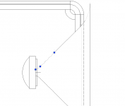
My idea is to mount the wave-guide into a lathe chuck or face plate, mount a dial indicator into the tool holder and use the cross-feed and compound locked to 90 deg. That is, move the compound in an increment, use the cross feed to move the dial indicator until it touches the wave-guide side and read the dials on the compound and the cross-feed.
I apologize for being so dense, but I still do not understand the problem. If I can obtain the wave-guide expansion, I can use the graphic tools that Marcel provided to adjust the variables for ATH4 to any degree of accuracy and, thus use the ATH.
I do appreciate your offer, but I cannot rely on other people to implement my idiotic ideas.
Although I can loft in CAD, I do not have the sheet-metal plugin so I cannot have the CAD determine the flat cut-out. But thinking about it, it appear to be just a geometry translation problem, so It can be tackled by math.
Kindest regards,
M
thank you again for your observations.
This is quite big I wonder if foamboard and fibreglass will work out. mark100 had trouble using this method of construction putting extra flares on one of his builds.
I do have same experience with such a structures, so I am rather confident that this might work. Look at the hand-launched airplane models, their wings are rather thin, they are subject to high forces on launch, yet they are built by this technology.
Regarding Mark, if I recall correctly, he had a problem with the joint between the plywood conical section and the Styrofoam end sections, and he did solve it.
Another thing to consider is the other drivers you intend to use and how they will be mounted. With this horn as a base 1" CD's are not going to go low enough to avoid some sort of mid-range driver. Where that needs to be mounted along the length might have a big impact on where you want to cut the B52.
Ah, ah, here I think I will face another doubts. I intend to use NSW2-326-8A. If Hornresponse model is any indication, four of them should get me close to 120 dB/1m, and given the drivers' small size, I think that I can pack in six of them if necessary. The frequency response on the specification sheet shows frequency response allowing 200Hz to 5kHz bandwidth.
I also have the drivers from the original Unity.
When I look at the spreadsheet the B52 does not look pure OS to me, trying to match that in Ath will be tricky and if you are off by more than a mm joining them correctly could be difficult.
There are two issues here. First, if one plays with the angle, one can get a fairly good match to about 80-90 mm from the throat. Second, I am not sure how accurate DonVK's curve is. I cut it from a cardboard, and the fit does not appear to be very good. So, I intend to remeasure it.
My idea is to mount the wave-guide into a lathe chuck or face plate, mount a dial indicator into the tool holder and use the cross-feed and compound locked to 90 deg. That is, move the compound in an increment, use the cross feed to move the dial indicator until it touches the wave-guide side and read the dials on the compound and the cross-feed.
If you worked out where you wanted to cut the horn then perhaps Don could be persuaded to assist in simulating an add on if you were able to create a CAD model of what you want.
I apologize for being so dense, but I still do not understand the problem. If I can obtain the wave-guide expansion, I can use the graphic tools that Marcel provided to adjust the variables for ATH4 to any degree of accuracy and, thus use the ATH.
I would offer my own help but I am building a machine to make waveguides and so I am tied up with that.
I do appreciate your offer, but I cannot rely on other people to implement my idiotic ideas.
The transition can be created in a CAD program by lofting along guide lines from the horn stub to the final size, making a rail for vertical and horizontal to follow is a simple 2D problem.
Although I can loft in CAD, I do not have the sheet-metal plugin so I cannot have the CAD determine the flat cut-out. But thinking about it, it appear to be just a geometry translation problem, so It can be tackled by math.
Kindest regards,
M
I don't think you are being dense so let me try a different way. If you have an exact replica of the curve(s), yes you can change the settings in Ath to try and match that/those curve(s) . In practice this is not so easy and can be very time consuming. There is no guarantee that any setting in Ath will produce the exact same shape as you measured in all three dimensions simultaneously.I apologize for being so dense, but I still do not understand the problem. If I can obtain the wave-guide expansion, I can use the graphic tools that Marcel provided to adjust the variables for ATH4 to any degree of accuracy and, thus use the ATH.
If this was an axisymetrical guide it would be easier.
Hi fluid,
thank you for your patience. i thing that we are on the same page now.
Kindest regards,
M
thank you for your patience. i thing that we are on the same page now.
Kindest regards,
M
- Home
- Loudspeakers
- Multi-Way
- Establishing B-52 PHRN-1014 conour?