Via ASIO drivers.Sorry I assumed because there was an AP logo in the graphs. How did you interface the Cosmos ADC to an AP?
"Is there a version of the AP software that runs on a PC without an AP unit being connected?" Yes for $$$$.
What I would like to see and could help illuminate what is going on is using DiAna to analyz the distortion at several points. If you follow its calibration routine with an APU in the chain it will correct for the insertuion loss of the APU and show the correct harmonic amplitues and phase relationship. It will also recreate the residual so its clear what part of the waveform departs from ideal and how. it can be very informative.
What I would like to see and could help illuminate what is going on is using DiAna to analyz the distortion at several points. If you follow its calibration routine with an APU in the chain it will correct for the insertuion loss of the APU and show the correct harmonic amplitues and phase relationship. It will also recreate the residual so its clear what part of the waveform departs from ideal and how. it can be very informative.
Today I got the scaler. It improves DAC measured performance at full scale (where it is automatic fix gain to 0db, hence a buffer),
but even more improvement at low levels when it can give much better THD numbers.
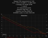
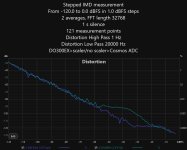
Anyway, I put the scaler into autorange mode, in between the DACDO300EX to Cosmos ADC in stereo mode (so results could be
even better by +3db, I don't have enough connectors). Here I give two measurements: IMD and THD swept.
In each picture I overlayed two graphs: one with scaler and one without, such that it is possible to compare the scaler influence.
As you can see, it improves. In both cases it reduces the hump and I think little shift it to the right, but maybe it is also a point where
ADC is overloaded. In any the higher DAC level is closer to the place where the scaler is a unity gain, or step above.
I did not include comparison to Nihtila AK5572, but I compared. I can tell, with respect to IMD, AK5572 without scaler is almost like Cosmos+scaler 🙂
In THD, AK5572 without scaler is little worse than Cosmos+scaler. I did not check AK5572 with scaler and in both cases I did not incorporated the
APU in THD tests here, so even possible better results could be reached.
but even more improvement at low levels when it can give much better THD numbers.
Anyway, I put the scaler into autorange mode, in between the DACDO300EX to Cosmos ADC in stereo mode (so results could be
even better by +3db, I don't have enough connectors). Here I give two measurements: IMD and THD swept.
In each picture I overlayed two graphs: one with scaler and one without, such that it is possible to compare the scaler influence.
As you can see, it improves. In both cases it reduces the hump and I think little shift it to the right, but maybe it is also a point where
ADC is overloaded. In any the higher DAC level is closer to the place where the scaler is a unity gain, or step above.
I did not include comparison to Nihtila AK5572, but I compared. I can tell, with respect to IMD, AK5572 without scaler is almost like Cosmos+scaler 🙂
In THD, AK5572 without scaler is little worse than Cosmos+scaler. I did not check AK5572 with scaler and in both cases I did not incorporated the
APU in THD tests here, so even possible better results could be reached.
Attachments
Very interesting even if I don't have an explanation for the observed behavior. Do we know when the scaler switched or what the respective input level into the ADC was? It is remarkable that there are no clear switching points as with Audio Precision sweeps except for -30 dB which could be a switch point or the hump.
Why would you get lower THD but not lower IMD with the scaler? The only thing I can imagine is that the bins for THD are still large enough to include some noise whereas those for IMD are sufficiently narrow.
Why would it dissappear the hump for -50 to -30 dB and make it smaller from -30 for both THD and IMD? I have no idea at this point!
For detailed on scaler behavior, please look here:
https://e1dashz.wixsite.com/index/cosmos-scaler
The DO300EX had 5V full scale and the scaler is targeted to 4.5V.
The x-axes is generator level, so you can compute more or less the DAC output and the gain setting from the table of gains in scaler webpage above.
When the graphs are cosmos direct to DAC or via scaler. So, you see that impact of loading more on THD for some reason. The THD swept with scaler is very similar to the same swept with APU Notch.
I think the impact I mentioned of loading the DAC (without scaler) does not enter the play as this loading more effect the harmonics to 19k and 20k, so higher that does not count. I think that the reason no a lot of benefit to IMD with scaler except the clear hump reduction.
The hump is maybe partly shifted because of the amplification I think. Shifted and also much reduced.
I presume the ADC was in 4.5 V range, i.e. 1.66 kOhms input impedance? Would this really degrade the THD of the DAC? Just loading the DAC output with a resistor while monitoring with the scaler and ADC would tell.
2.46 kOhms, then. I would have expected better from the output buffer of a high end DAC.
The Nihtila has 2x 100 k input impedance according to the schematic of the 1.1 version, so exactly like the scaler.
The Nihtila has 2x 100 k input impedance according to the schematic of the 1.1 version, so exactly like the scaler.
I will check but I am sure it is also loading. You can see the benefit is mostly at low levels, lower than hump interval. This could be also because the ADC has lower performance at low levels where the amplification counts. Near the end of measurement scaler gain is 0 or 7db and the benefit is almost none.
Not sure why the ADC should have poor distortion performance at low level. Usually they are excellent in that range but noise becomes an issue.
Just another idea: in addition to loading the DAC output with ~ 2.5 kOhms and measuring with the Nihtila, maybe you can run them in parallel (and without the extra resistive load)? If you see a difference between resisitive and Cosmos ADC load, this would tell you that the Cosmos ADC injects transients into its load. I haven't seen a schematic for the Cosmos' front end, but I wouldn't be surprised if an op amp with a low impedance feedback network were not able to fully isolate a switched load on its output from its input.
Just another idea: in addition to loading the DAC output with ~ 2.5 kOhms and measuring with the Nihtila, maybe you can run them in parallel (and without the extra resistive load)? If you see a difference between resisitive and Cosmos ADC load, this would tell you that the Cosmos ADC injects transients into its load. I haven't seen a schematic for the Cosmos' front end, but I wouldn't be surprised if an op amp with a low impedance feedback network were not able to fully isolate a switched load on its output from its input.
(Stock) filters vs time behavior vs output mode?Yes, the plot is just meant for illustration with a way exaggerated error. In reality, even for a DAC with a large hump the ripple is microscopic, not visible in a derived transfer function graph.
The error pattern might resemble a bit the known one for missing lower bits (which would produce a staircase) but actually its a sine-like error pattern. When I investigated the ESS hump in a DAC that has a massive hump the Eureka moment was when I looked at the distortion residuals with most of the noise removed.
Residual plot taken from my thread https://www.audiosciencereview.com/...-hump-revisited-khadas-tone-board-v1-3.30136/, at 0dBFS:
View attachment 1127675
We can see a sinusodial ripple overlay in the residual whose momentary frequency scales precisely with the momentary slope of the exiting sine wave... which I later managed to model with a piece of software which just adds a sinusodial ripple to a sample-in --> sample-out transfer function: https://www.audiosciencereview.com/...-hump-style-distortions-to-audio-files.30758/
With a bit of tinkering on scale factors and error magnitude I got really close to the measured results for that DAC under test.
The number of periods of the ripple function correlates with number of bits of the final internal DAC chip output stage (like 6 bit, 64 thermometer-coded switched current cells). Once the excitation sine signal spans more than one segment of the final stage, the ripple starts to appear and the hump will start to appear in THD+N vs level plots (or IMD+N, for that matter). I also found that the residual (and spectrum) characteristic is cyclic vs. added small DC. When this DC has just the level of one segment (1/64th of full scale) I got an exact copy of the zero DC graphs. Same goes for adding one segment of DC to a DC offset of X, same plots as with just X alone.
Extending this, the higher the level of the sine, the more segment transitions take place and the higher in frequency the spray of harmonics will, at lower relative levels for the individual harmonics (wrt to the fundamental) and that's why the hump "disappears" again once a certain level is reached.
-----:-----
Now this was for a DAC device with bad I/V converters where most of the error come from the I/Vs. But it turned out the characterstic ripple is still there even in better designed ESS DACs. Lower in level but still the same inner structure of the patterns. The 1kHz spectrum plots we get to see for pretty much any ESS-based product (at ASR and here at DIYA) at or close to 0dBFS all have the same signature pattern in the spray of harmonics.
Combining all this makes me think that there is a very systematic root cause in the D/S-modulation scheme of ESS products. @bohrok2610 has found that the harmonic amplitudes scale with clock frequency of the final DAC stage which thickens the plot, strongly pointing to glitch energy. The glitch energy injected to the I/V and getting integrated (or worse, demodulated) there is not constant (which would produce simple DC) but seems to vary while the signal wanders through segment transitions, at least that's the working hypothesis at the moment.
Therefore, if we can balance out the glitch energy by adding channels with specific small DC-offsets, the spurs will be reduced, and both spectrum and time residual will be much cleaner. I'm working on an experimental proof, as noted, but obviously it's not a simple walk in the park (I still have a day job).
Not sure what the question is....(Stock) filters vs time behavior vs output mode?
Funny things happeining with some ES...
Implementations aside, I found one strange curious behaviour when I trying to adjust bias from my DIY Stax amplifier with 4P1L tube outputs, using the ES9018K2M as a integrated internal DAC (partial voltage mode; loaded with some resistor). I noticed something odd, visible even if the tube system not have ultra low noise floor, and then saved it:
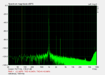
First, -100dB signal:

Then a 0dB signal:

The noise floor rises, and I know that NOT being from the tubes (unlees they parasitic oscillate).
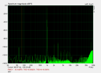
With 30Hz signal, the noise floor have a slope:

With multitone signal, the noise floor reduces drastically towards lower frequencies:

The signal generator are form ARTA, using the Asus Xonar board with ASIO.
I not investigated the amplitude vs signal applied to see if it also have the hump. STEPS from ARTA can be able to measure this I believe. Next week I can play with it, since I will I remove it from inside of my phone amp for using external DAC (I will be using it now: https://www.diyaudio.com/community/threads/valve-dac-from-linear-audio-volume-13.308860/ ).
This variable noise floor...
Can be due do implementation (board maker), or because I use Voltage out (the board is one from DIYINHK)?
Implementations aside, I found one strange curious behaviour when I trying to adjust bias from my DIY Stax amplifier with 4P1L tube outputs, using the ES9018K2M as a integrated internal DAC (partial voltage mode; loaded with some resistor). I noticed something odd, visible even if the tube system not have ultra low noise floor, and then saved it:
First, -100dB signal:
Then a 0dB signal:
The noise floor rises, and I know that NOT being from the tubes (unlees they parasitic oscillate).
With 30Hz signal, the noise floor have a slope:
With multitone signal, the noise floor reduces drastically towards lower frequencies:
The signal generator are form ARTA, using the Asus Xonar board with ASIO.
I not investigated the amplitude vs signal applied to see if it also have the hump. STEPS from ARTA can be able to measure this I believe. Next week I can play with it, since I will I remove it from inside of my phone amp for using external DAC (I will be using it now: https://www.diyaudio.com/community/threads/valve-dac-from-linear-audio-volume-13.308860/ ).
This variable noise floor...
Can be due do implementation (board maker), or because I use Voltage out (the board is one from DIYINHK)?
Attachments
I just made some measurements in another ES9018 board that I have. Is the same from my other measurements, but is using USB instead of S-PDIF, but don't have dedicated PSU, is using the USB supply regulated by a mundane 1117 reg (USB power... that's HORRIBLE, BTW; needs a serious filtering). But I made this as an emergency DAC, and in reality I use more the S-PDIF output from the USB part (XMOS), for feeding another DAC.
BTW. My phones amp have only S-PDIF input. I dunno if it cause some difference, also.
Since I made a very compact layered phone amp, is horrible to play with, so I will play when I open it again for the mentioned changing... for now, the stand-alone ES (voltage mode, USB input):
The noise floor from the "emergency" DAC (for reference):

With signal:

30Hz:

-90dB:

Multitone:

The noise behaviour differs drastically from the phones amp, and now have a 20kHz bump. Perhaps from the noise from another IC's. But basically not shows the variable noise floor. The board have separated AVCC power pins, that I used for my trusty TL431 reg for the phones one (I used that reg for a miriad of another DACs, including some very sucessful. For this DAC I simply filtered a little the 3V3 for using it with USB. But anyway, since it seems to be very sensitive to supply, will be at my to-do list to test it with phones ES DAC, to see if the supply there have some misbehaviour, along with the linearity bump one.
I'm unable to test the steps now, since I don't have isolated USB and the loop from same PC is horrendous; very noisy, invalidating the measurements. And using the notebook with another ARTA like I used here not works for STEPS due to lack of sync (but worked for static measurements).
BTW. My phones amp have only S-PDIF input. I dunno if it cause some difference, also.
Since I made a very compact layered phone amp, is horrible to play with, so I will play when I open it again for the mentioned changing... for now, the stand-alone ES (voltage mode, USB input):
The noise floor from the "emergency" DAC (for reference):
With signal:
30Hz:
-90dB:
Multitone:
The noise behaviour differs drastically from the phones amp, and now have a 20kHz bump. Perhaps from the noise from another IC's. But basically not shows the variable noise floor. The board have separated AVCC power pins, that I used for my trusty TL431 reg for the phones one (I used that reg for a miriad of another DACs, including some very sucessful. For this DAC I simply filtered a little the 3V3 for using it with USB. But anyway, since it seems to be very sensitive to supply, will be at my to-do list to test it with phones ES DAC, to see if the supply there have some misbehaviour, along with the linearity bump one.
I'm unable to test the steps now, since I don't have isolated USB and the loop from same PC is horrendous; very noisy, invalidating the measurements. And using the notebook with another ARTA like I used here not works for STEPS due to lack of sync (but worked for static measurements).
AVCC supply on ESS dacs is the most critical. Typical recommendation in datasheets is to use an ultra-low noise LDO. It may be that your TL431 regulator has too high 1/f noise and is not suited for AVCC.
After seeing the bad results for the simple one, I'm more than convinced (these thing when we see for oneselves)...
I can built a low noise shunt if it benefits the ES. I already built some:
TL shunt:

Discret shunt (different scale):

My unbalanced gig sometimes have some airborne noise, but the noise floor from this last rivals with my measuremen gig ADC noise floor. Perhaps will suffice for the ES (I hope, then)....
I can built a low noise shunt if it benefits the ES. I already built some:
TL shunt:
Discret shunt (different scale):
My unbalanced gig sometimes have some airborne noise, but the noise floor from this last rivals with my measuremen gig ADC noise floor. Perhaps will suffice for the ES (I hope, then)....
- Home
- Design & Build
- Equipment & Tools
- ESS hump strikes back