Sorry for the clickbait title as this is not really about ESS hump. Or is it?
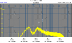
As I was testing my ES9822PRO board I noticed that the 1kHz FFT spectrum has high harmonics up to 100kHz and beyond.
Here is ES9038Q2M to ES9822PRO.

The harmonics of 1kHz continue throughout the spectrum albeit at a low level.
So are these harmonics coming from the DAC or the ADC?
Here is the same ES9038Q2M DAC but with AK5394 as ADC (fs is now 96kHz).

So it seems DAC is the culprit. Or is it?
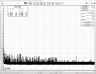
To verify I switched to a 1kHz oscillator (my take on Victor's). Here is 1kHz oscillator + AK5394.

As expected spectrum is quite clean.
Let's repeat that measurement with ES9822PRO.

Surprise, surprise. The 1kHz harmonics are back. Also ES9822PRO has high harmonics.
So it appears that ESS architecture (Hyperstream?) causes high harmonics both in DACs and ADCs. Is this the cause for the infamous ESS sound?
As I was testing my ES9822PRO board I noticed that the 1kHz FFT spectrum has high harmonics up to 100kHz and beyond.
Here is ES9038Q2M to ES9822PRO.
The harmonics of 1kHz continue throughout the spectrum albeit at a low level.
So are these harmonics coming from the DAC or the ADC?
Here is the same ES9038Q2M DAC but with AK5394 as ADC (fs is now 96kHz).
So it seems DAC is the culprit. Or is it?
To verify I switched to a 1kHz oscillator (my take on Victor's). Here is 1kHz oscillator + AK5394.
As expected spectrum is quite clean.
Let's repeat that measurement with ES9822PRO.
Surprise, surprise. The 1kHz harmonics are back. Also ES9822PRO has high harmonics.
So it appears that ESS architecture (Hyperstream?) causes high harmonics both in DACs and ADCs. Is this the cause for the infamous ESS sound?
Last edited:
Given the spread of harmonics (ie how far across the spectrum without loosing power) they really look like a square wave interacting with the input signal. Is there any digital filter enabled? I've seen some noise paper related to filters causing additional harmonics.
I agree though it could well be quantisation noise (https://www.researchgate.net/public..._between_sampling_rate_and_quantization_noise)
I agree though it could well be quantisation noise (https://www.researchgate.net/public..._between_sampling_rate_and_quantization_noise)
Last edited:
None of your images show anything over 100kHz??I noticed that the 1kHz FFT spectrum has high harmonics up to 100kHz and beyond.
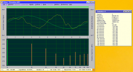
On the one hand do harmonics or noise below -110 dB matter? However it may when looking at a more complex signal. The AK5394 is a remarkable ADC. I have had similar results. Unfortunately the chip is discontinued. Possibly some IM type of signal would show higher levels of distortions. Also would be interesting to look at transient response. Below for reference is my Victor to Shibasoku and the Victor to AK5394 (Using Diana). Diana lists the harmonic amplitudes to the 14th.
Attachments
Correct. I made that assessment based on earlier measurement I made with the same devices at 33.69Hz. In that measurement high harmonics can be seen up to 12kHz. So assuming similar behaviour at 30 times higher frequency higher harmonics could go beyond 100khz (only 8 times higher than 12kHz).None of your images show anything over 100kHz??
Attachments
Yes it is.Sorry for the clickbait title as this is not really about ESS hump. Or is it?
All ESS products have a characterstic ripple in the sample-in --> sample-out transfer function which basically looks like this:
The ripple is periodic (self-similar).
Add some DC to a (largish) test signal and the levels and phases of the distortion components shift around but the total energy remains the same.
This also shows us the way for a potential fix: add (at least) two channels after applying proper small DC digital (or analog, for the ADC) offsets to cancel out the wobbles in effect. The wobbles come from the final DAC output which is 5 or 6 bits.
I've tried the concept with ES9038q2m but sadly channel matching wrt to residual is systematically bad, and chip to chip matching also isn't great. Therefore I had to use the same channel and then cancelling was very effective (for all signal levels and frequencies as the error is systematic and not signal-dependent).
We might need to use one of 8-channel devices and find the sets of channels which do match well and then I would expect 20dB of reduction of spurs should be possible. Sadly, no commercial 8-ch units like Topping DM7 have a means to sync a recording device which make the required time-domain-averaging (to clearly expose the residuals inner structure) almost impossible... and thus no way to directly analyse the residual or verify the success, other by looking at resulting spectra.

I did find this which is very good https://www.ieee.li/pdf/viewgraphs/jitter_basics_advanced.pdf which includes the transfer function.
Yes, the plot is just meant for illustration with a way exaggerated error. In reality, even for a DAC with a large hump the ripple is microscopic, not visible in a derived transfer function graph.I would think that ripple would generate a lot of high order harmonics. Is your example an exaggerated representation? It looks like missing low order bits.
The error pattern might resemble a bit the known one for missing lower bits (which would produce a staircase) but actually its a sine-like error pattern. When I investigated the ESS hump in a DAC that has a massive hump the Eureka moment was when I looked at the distortion residuals with most of the noise removed.
Residual plot taken from my thread https://www.audiosciencereview.com/...-hump-revisited-khadas-tone-board-v1-3.30136/, at 0dBFS:
We can see a sinusodial ripple overlay in the residual whose momentary frequency scales precisely with the momentary slope of the exiting sine wave... which I later managed to model with a piece of software which just adds a sinusodial ripple to a sample-in --> sample-out transfer function: https://www.audiosciencereview.com/...-hump-style-distortions-to-audio-files.30758/
With a bit of tinkering on scale factors and error magnitude I got really close to the measured results for that DAC under test.
The number of periods of the ripple function correlates with number of bits of the final internal DAC chip output stage (like 6 bit, 64 thermometer-coded switched current cells). Once the excitation sine signal spans more than one segment of the final stage, the ripple starts to appear and the hump will start to appear in THD+N vs level plots (or IMD+N, for that matter). I also found that the residual (and spectrum) characteristic is cyclic vs. added small DC. When this DC has just the level of one segment (1/64th of full scale) I got an exact copy of the zero DC graphs. Same goes for adding one segment of DC to a DC offset of X, same plots as with just X alone.
Extending this, the higher the level of the sine, the more segment transitions take place and the higher in frequency the spray of harmonics will, at lower relative levels for the individual harmonics (wrt to the fundamental) and that's why the hump "disappears" again once a certain level is reached.
-----:-----
Now this was for a DAC device with bad I/V converters where most of the error come from the I/Vs. But it turned out the characterstic ripple is still there even in better designed ESS DACs. Lower in level but still the same inner structure of the patterns. The 1kHz spectrum plots we get to see for pretty much any ESS-based product (at ASR and here at DIYA) at or close to 0dBFS all have the same signature pattern in the spray of harmonics.
Combining all this makes me think that there is a very systematic root cause in the D/S-modulation scheme of ESS products. @bohrok2610 has found that the harmonic amplitudes scale with clock frequency of the final DAC stage which thickens the plot, strongly pointing to glitch energy. The glitch energy injected to the I/V and getting integrated (or worse, demodulated) there is not constant (which would produce simple DC) but seems to vary while the signal wanders through segment transitions, at least that's the working hypothesis at the moment.
Therefore, if we can balance out the glitch energy by adding channels with specific small DC-offsets, the spurs will be reduced, and both spectrum and time residual will be much cleaner. I'm working on an experimental proof, as noted, but obviously it's not a simple walk in the park (I still have a day job).
Last edited:
Amazing work. I'm impressed with what you managed to do. I'm concerned that any correction algorithm with need to be tuned to the specific example of the chip and may need temperature compensation. Phofman's work on correction at a single frequency seems to support the very narrow balancing act needed.
A separate observation- most linear/analog process test to not generate higher harmonics. Those only surface when something moves through a transition (crossover distortion, voice coil rubbing). And we humans seem to have a high tolerance for the low order distortions ( I have seen reports of up to 5% not being objectionable) but higher order distortions at low levels really seem to get noticed somehow.
It seems inconceivable that the distortions of the ESS chips are inaudible but they well may be. I believe the ESS chips have a lot of out of band stuff as well. And even Scott Wurcer pointed out how much wishful thinking it was to believe a normal opamp could manage filtering 100 MHz glitches on the input. FWIW I had really good success with an LC filter on the output of AKM voltage output DACs. That's harder to do with a current output DAC.
Is this all mainly with ES9038Q2M? What about ES9028 and ES9018? Exactly the same, less or even none at all? Maybe it is good to make that distinction (if so).
Being already tough information as it is... when people start believing things we may see ritual burnings of ESS DACs.
Being already tough information as it is... when people start believing things we may see ritual burnings of ESS DACs.
Last edited:
These 6bit conversion segments - maybe they could be mapped onto the input 32bit digital values into the DAC. Maybe this mapping is static and constant for a given DAC model. If so, maybe the transfer function could be pre-distorted in the digital domain. Maybe some corrective algorithm with feedback control could be used to finetune the compensation for the specific piece and application.
Predistorting transfer characteristic will have the usual problem of needing very specific trim and being not universal, having frequency dependence etc.These 6bit conversion segments - maybe they could be mapped onto the input 32bit digital values into the DAC. Maybe this mapping is static and constant for a given DAC model. If so, maybe the transfer function could be pre-distorted in the digital domain. Maybe some corrective algorithm with feedback control could be used to finetune the compensation for the specific piece and application.
Therefore I think using the similar (ideally: identical) distortion as is from several channels and "cancel" it by clever summing of offseted(sp?) transfer characteristic is a better approach which should be much more stable and might not even need a trim at all. To the extent that the transfer ripple on different channels is self-similar and is well-centered this should work out.
ES9023 under investigation atm. This is a self-contained DAC with I/V OpAmp stages on-chip, though. And those OpAmp outputs have to loaded with 4.7nF as per datasheet to tame the RF output at least somewhat, it seems.Is this all mainly with ES9038Q2M? What about ES9028 and ES9018? Exactly the same, less or even none at all? Maybe it is good to make that distinction (if so).
Being already tough information as it is... when people start believing things we may see ritual burnings of ESS DACs.
As for that, what I found is that the mapping spans only a part of the 6bit range in the ES9038q2m. In the hump emulator I wrote the span is only ~26.5 cycles, not 32 cycles (for the [0..1] range, used symmetrically) as one would expect. That is, not 100% modulation depth (on average).These 6bit conversion segments - maybe they could be mapped onto the input 32bit digital values into the DAC. Maybe this mapping is static and constant for a given DAC model.
The number of bits for the final output can be register-programmed, btw.
I'm not yet quite ready for burning my ESS DAC chips but I have 3 ES9311Qs I'm more than happy to throw in the bonfire.... when people start believing things we may see ritual burnings of ESS DACs.
Happy camper here with ES9028Q2M. Liked a few AKM DAC types only slightly better or found practically no difference depending on type.
What is wrong with ES9311Q?! Did not even know of their existence. The ESS marketshare and dominance caused a lack of appetite to be honest.
What is wrong with ES9311Q?! Did not even know of their existence. The ESS marketshare and dominance caused a lack of appetite to be honest.
Last edited:
- Home
- Design & Build
- Equipment & Tools
- ESS hump strikes back