The part you mention above appears to be unobtainium. If there is an alternative you know of offhand that is available from Mouser or Digikey I might be willing to give that approach a try.
Otherwise, clock divider chips appear to be what can be reasonably obtained.
Assuming tests over the next few days show good effects on sound quality, then a low cost, easy to find and use solution that does the dividing would be probably be worth spending some time searching around for. Otherwise, some kind of circuit boards would be needed for ball-grid-array parts, or other cook-on-solder-pad parts.
For Potato Semi ->
7474 G Series GHz TTL CMOS logic IC 14pin SOIC QTY-1 | eBay
Other than that I would use LVC
http://www.ti.com/lit/ds/symlink/sn74lvc1g74.pdf
Edit - not sure if dual FF is available in LVC.
I have rarely seen logic phase noise comparisons.
http://www.ham-radio.com/sbms/LPRO-101.pdf
Check page 17/18/19
As you can see, a 74AC inverter does not degrade phase noise of -130dBc at
10Hz offset. This is super low and I think LVC or potato would be at least as
good. Obviously a flip flip will have worse phase noise than an inverter... )I
think) 🙂
T
Last edited:
Obviously a flip flip will have worse phase noise than an inverter... )I
think) 🙂
I think so too. How it would affect DPLL stability and sound quality would be the things I would want to find out. It would certainly be cheaper and easier as compared to using a fancy clock divider chip.
However, don't know how much I trust ebay sellers to deliver what I order when it comes to ICs. And, I wouldn't want people modding here not to be able to be sure of what they might be getting either. It can be hard enough to do one of these rather involved projects without having to wonder about fake parts.
EDIT: Regarding SN74LVC1G74, at least there is a Surfboard adapter for the DCT package. The IC would pretty tiny to work with without something like that to help prototype with it. Looks like they sell the IC at Digikey.
Depending on how things turn out when I get all set up to do sound quality listening tests and comparisons using the existing divider chip, a next step might be to try making a simple filp-flop divider and see how well that might work.
Last edited:
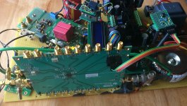
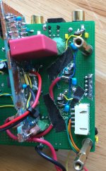
Starting to make some progress with getting the clock divider mod ready for careful listening tests. Have to rearrange some things physically to get everything mounted on one test platform. Also, it is getting to the point with this mod where I can't really keep using the original Chinese ES9038Q2M dac board MCU. Up until this point I have been able to switch back and forth between original MCU control and Arduino. As it happens if I try that with the current dac chip register settings, the original MCU will reset them immediately upon returning control to it, which effectively stops operation of the AK4137 board. So, will have to write some more Arduino code to boot up the dac board and make volume control adjustments using Arduino only. A couple of pics below show the current state of preparations.
Attachments
Flip-flop clock divider
Check out the Nexperia 74ALVC74D, available at digikey in SO14 (0.05inch pitch), easier to solder, and has potentially better characteristic, than the TI LVC.
74ALVC74D,112 Nexperia USA Inc. | Integrated Circuits (ICs) | DigiKey
Check out the Nexperia 74ALVC74D, available at digikey in SO14 (0.05inch pitch), easier to solder, and has potentially better characteristic, than the TI LVC.
74ALVC74D,112 Nexperia USA Inc. | Integrated Circuits (ICs) | DigiKey
However, don't know how much I trust ebay sellers to deliver what I order when it comes to ICs.
I believe that's the Potatosemi official end-user purchase channel (it's linked on their web site).
Hi wealas,
Interesting, thanks for mentioning that. Looks like I may be shopping for some flip-flops pretty soon.
Interesting, thanks for mentioning that. Looks like I may be shopping for some flip-flops pretty soon.
Hi Mark,
Great to read that your ak4137 mod is working.
Curious to read your feeling about SQ.
I have a question:
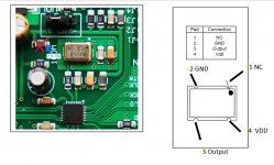
Do you think it is a good thing to add a dedicated regulator to the new clock i installed?(Crystek CCHD-575-50)
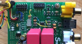
Could you tell me if this pictur(osc4.jpg) is right about where to solder the +3.3v please?
Where do you think I should connect the GND? directly on the pin 2 of the clock? Or is it a better place to solder it?
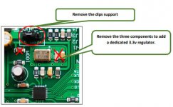
I checked Sergelisses pdf, but he removed more smd composants than on your pictures, and the pictures are not really clear about where he soldered.
Thank you
Great to read that your ak4137 mod is working.
Curious to read your feeling about SQ.
I have a question:
Do you think it is a good thing to add a dedicated regulator to the new clock i installed?(Crystek CCHD-575-50)
Could you tell me if this pictur(osc4.jpg) is right about where to solder the +3.3v please?
Where do you think I should connect the GND? directly on the pin 2 of the clock? Or is it a better place to solder it?
I checked Sergelisses pdf, but he removed more smd composants than on your pictures, and the pictures are not really clear about where he soldered.
Thank you
Attachments

Hi terrry22,
Yes, a dedicated regulator does help sound quality a little more. I added three dedicated LT1763 regulators to the underside of the ground plane at the digital end of the dac board for the clock, for VCCA, and for DVCC. Some pictures showing what it looked like with the first two of those regulators installed can be found at the following post: https://www.diyaudio.com/forums/digital-line-level/314935-es9038q2m-board-301.html#post5577671
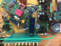
I will post a couple more pics below showing the 3rd LT1763 mounted on the bottom of the ground plane and wiring bringing power up to the clock. The clock power can be connected on either side of the inductor, as you prefer. (Actually, location of the inductor depends on the dac board. For the pictures below it is down near the original voltage regulator, but I cut the trace going down there.) Currently, I have power connected to the output side of the inductor, or it would be if the inductor were located down in the filter cap area on this board (the 3 SMD parts next the clock are a .1uf X7R, a 15uf or 10uf tantalum, and a small inductor, with the inductor being the most distant from the clock). Also, the ground side of a regulator can be connected to the ground plane near the clock, it doesn't have to be right on the clock ground pin.
You may also notice that in one of the pictures below I replaced the .1uf ceramic and the original 15uf tantalum caps with my own better quality .1uf ceramic and a 10uf tantalum polymer at the far side of the dac chip. The latter cap was too big to fit on the pads normally, so I soldered it on its side. Eventually, I also replaced the corresponding caps at the clock the same way. Don't know if it matters all that much though. It was an experiment, but I think it may have improved frequency stability some. (Please recall the the pics can be blown up to full size by clicking on the white x in the lower left corner.)
Yes, a dedicated regulator does help sound quality a little more. I added three dedicated LT1763 regulators to the underside of the ground plane at the digital end of the dac board for the clock, for VCCA, and for DVCC. Some pictures showing what it looked like with the first two of those regulators installed can be found at the following post: https://www.diyaudio.com/forums/digital-line-level/314935-es9038q2m-board-301.html#post5577671
I will post a couple more pics below showing the 3rd LT1763 mounted on the bottom of the ground plane and wiring bringing power up to the clock. The clock power can be connected on either side of the inductor, as you prefer. (Actually, location of the inductor depends on the dac board. For the pictures below it is down near the original voltage regulator, but I cut the trace going down there.) Currently, I have power connected to the output side of the inductor, or it would be if the inductor were located down in the filter cap area on this board (the 3 SMD parts next the clock are a .1uf X7R, a 15uf or 10uf tantalum, and a small inductor, with the inductor being the most distant from the clock). Also, the ground side of a regulator can be connected to the ground plane near the clock, it doesn't have to be right on the clock ground pin.
You may also notice that in one of the pictures below I replaced the .1uf ceramic and the original 15uf tantalum caps with my own better quality .1uf ceramic and a 10uf tantalum polymer at the far side of the dac chip. The latter cap was too big to fit on the pads normally, so I soldered it on its side. Eventually, I also replaced the corresponding caps at the clock the same way. Don't know if it matters all that much though. It was an experiment, but I think it may have improved frequency stability some. (Please recall the the pics can be blown up to full size by clicking on the white x in the lower left corner.)
Attachments
Last edited:
Hi terrry22,
Yes, a dedicated regulator does help sound quality a little more. I added three dedicated LT1763 regulators to the underside of the ground plane at the digital end of the dac board for the clock, for VCCA, and for DVCC. Some pictures showing what it looked like with the first two of those regulators installed can be found at the following post: https://www.diyaudio.com/forums/digital-line-level/314935-es9038q2m-board-301.html#post5577671
I will post a couple more pics below showing the 3rd LT1763 mounted on the bottom of the ground plane and wiring bringing power up to the clock. The clock power can be connected on either side of the inductor, as you prefer. (Actually, location of the inductor depends on the dac board. For the pictures below it is down near the original voltage regulator, but I cut the trace going down there.) Currently, I have power connected to the output side of the inductor, or it would be if the inductor were located down in the filter cap area on this board (the 3 SMD parts next the clock are a .1uf X7R, a 15uf or 10uf tantalum, and a small inductor, with the inductor being the most distant from the clock). Also, the ground side of a regulator can be connected to the ground plane near the clock, it doesn't have to be right on the clock ground pin.
You may also notice that in one of the pictures below I replaced the .1uf ceramic and the original 15uf tantalum caps with my own better quality .1uf ceramic and a 10uf tantalum polymer at the far side of the dac chip. The latter cap was too big to fit on the pads normally, so I soldered it on its side. Eventually, I also replaced the corresponding caps at the clock the same way. Don't know if it matters all that much though. It was an experiment, but I think it may have improved frequency stability some. (Please recall the the pics can be blown up to full size by clicking on the white x in the lower left corner.)
Thank you Mark for the info and the pictures.
Last edited:
KoAP, Very unlikely that would work. DSD256 can be produced using either of the two common audio clock frequencies used to produce 44.1kHz or 48kHz, or their higher multiples. The closest standard clock frequency to what I am doing that might be used with AK4137 would be 24.576MHz, which corresponds to the 48kHz family version of DSD256. Increasing the clock frequency a little higher to 25MHz is not all that much in the way of overclocking. On the other hand, increasing the clock to 50MHz would be a huge jump and way higher AK4137 was ever designed to work. Therefore, probably not worth spending any time working on. Someone else can, though. 🙂
Last edited:
Clock Divider Works as Intended!
Just got the dac up and running through the AHB2 power amp. Using the clock divider to phase lock the ES9038Q2M and AK4137 clocks allows DPLL bandwidth to be dead stable at a setting of one. As before when doing this type of thing, still find that dac sound quality may be subjectively a little better with DPLL bandwidth set to 2 or 3.
So far, nothing else has been tweaked in dac registers. The main thing I should probably do next would be to get an FFT going and adjust harmonic distortion compensation for minimum distortion, and also see if that is subjectively the best setting. I think it probably would be except for the possible presence of any higher order harmonic distortion. In that case, a little bit of H2 and or H3 can help to mask or otherwise compensate to make the higher harmonics sound less objectionable.
I also should get some flip-flops on order to find out if higher jitter clock frequency locking can work well enough and help keep down cost and complexity.
In terms of cost, clock divider chips cost around $15 - $18 in small quantities and they don't need much in the way of support chips, although they do need to programmed. Since there will always have to be some kind of MCU to work with the dac chip, the only other issue might be that the clock divider chip I used has to be programmed over SPI bus vs the dac chip which uses I2C bus.
The other issue with clock divider chips is that they can't be hand soldered due to an unexposed solder pad on the bottom of the chip for heat sinking and maybe for additional grounding. Although, I guess I might try prototyping an IC adapter board with a hole left under a divider chip to hand solder the then exposed pad. In that case some copper foil could keep a low impedance ground to the board ground plane. Would have to think some more about heat sinking if I were to try that.
Otherwise, we would need to make a PCB and develop a reliable process for cooking on chips. Either that, or find a board manufacturer that could solder some or all of the parts on boards they make, or something like that. However, in that type of situation I wouldn't want to legally become a manufacturer and or an exporter myself. So, there would have to be some other alternative way to make the parts available.
Last edited:
Can't Celebrate Yet, However...
Just found another issue with the test setup that I think I will have to work on before anything else. I have noticed before that the dac sound quality is sensitive to RF fields in the local area. For example, the desktop computer nearby with a big window in one side to show off the motherboard can cause problems.
Similarly, I just noticed that turning on power to the clock divider and the maybe just the LVCMOS to LVDS converter hanging in air has a similar adverse affect on dac sound quality. So, have to solve that problem next I think.
It could also turn out that using a little flip-flop divider would be far better in terms EMI/RFI to manage. I am sure the problem can be solved, of course, and some attention should be given to it in any case since many other devices could potentially cause sound quality problems due to the sensitivity.
Last edited:
Decided to try soldering the LVCMOS to LVDS converter board ground plane to the dac ground plane down at the bottom side of the digital end of the dac board. However, spare real estate down there is starting to run in fairly short supply, so I kind of had to put it sticking out a little from under the side of the dac board near one corner.
The reason for trying the above is to find out if mounting the little board on the big board and soldering the ground planes together will keep the little board form acting like a broadcast antenna, and or so much of a possible source of problematic ground currents.
During some simple tests earlier, it kind of looked like the RF noise issue I noticed this morning was related to the little converter board being powered on. Even without the clock divider programmed to enable any outputs or do any dividing, there was already RF-caused distortion on the dac outputs when the clock divider and converter board were nothing more than powered on. If what I just did turns out to help, but not completely fix the problem it could be it would help more to get the converter board off the clock divider 3.3v power supply and give it its own little dedicated 3.3v regulator on the dac board. We'll see. Hopefully, I will get it sorted out tomorrow or at least within the next few days.
Just to hedge my bets, I also ordered some flip-flops from Potato and from Digikey (which I will try even if the clock divider board is working fine). One way or another I think it should be possible to get this clock divider mod working pretty soon in order to get another step up in sound quality, and then move on to the last thing I am interested in seeing if we can do, which is, of course, to improve interpolation filtering sound quality. No promises on that one, though. I am still not keen on the prospect of writing a lot of low level VHDL code.
Last edited:
Quick update on clock divider mod developments: Tests continue to show some low-level high-order harmonic distortion (that's what it sounds like anyway) when, (1) LVCMOS to LVDS adapter board is powered from the other side of the test setup, where it picks up 3.3v from the clock divider power supply, and or (2) depending on the power transformer or wall wart DC supply used as input power for the Chinese LT3042 with pass transistor 3.3v power supply for the clock divider board. For item (1) the plan is to add another dedicated LT1763 regulator on the dac board with a pin header jumper to allow testing with the regulator enabled or disabled in order to see if any distortion is caused by LVCMOS to LVDS adapter. For item (2), an R-core power transformer designed for dac use was found to create no audible-to-me increase in dac audio output distortion when used as input power source for the (now dedicated) clock divider board LT3042 3.3v power supply, so the transformer will be permanently added to the standard test setup.
In addition, the LVCMOS to LVDS adapter board is soldered on its edge to dac ground plane much like the AVCC board is. As with the AVCC board, the little adapter board will require fabrication of a little bit mechanical bracing to stabilize it against stress damage from attaching/detaching u.fl connectors, etc.
What all the foregoing means is there is more testing to do, and more work to do first to prepare for more testing. Thus, it will likely take another day or two before it is known if the clock-divider-power-supply-related distortion issues have been fixed.
If no satisfactory operation can be achieved with the current physical board layout of the test platform, then an alternate layout will be considered for the purpose of improving isolation and reducing stray coupling between clock signal related circuitry and dac board analog circuitry. Of course, if I were starting from scratch knowing what I know now I would probably plan board-level physical layout out rather differently from way things kind naturally happened to fall into place over the course of some months of project development.
Last edited:
Check out the Nexperia 74ALVC74D, available at digikey in SO14 (0.05inch pitch), easier to solder, and has potentially better characteristic, than the TI LVC.
74ALVC74D,112 Nexperia USA Inc. | Integrated Circuits (ICs) | DigiKey
Agreed, the Nexperia ALVC looks really good and an upgrade from LVC.
However, I think ultimately, when you get to these speeds, the phase noise
performance will be largely determined by layout, ground plane, decoupling
and power supply. But better of starting with a superior part.
The only way I would use any of these parts is with a solid ground plane.
The only way I would use any of these parts is with a solid ground plane.
Agreed, that's what we do.
Mark,
thank you for reply
would you please tell me why there Is no crystal/XO In the following AK4118 digital receiver board NEW AK4118 digital receiver board SPDIF input switch IIS with IIS support XMOS | eBay
does having no crystal/XO relates to limited supported sampling rates
thank you for reply
would you please tell me why there Is no crystal/XO In the following AK4118 digital receiver board NEW AK4118 digital receiver board SPDIF input switch IIS with IIS support XMOS | eBay
does having no crystal/XO relates to limited supported sampling rates
Hi samoloko,
The board I linked to for some possible help with interconnection instructions does not support SPDIF input, only I2S. It can output right justified, however.
There is another sample rate converter that does support SPDIF input and output right justified, but it is more expensive. It is this type: HIFI AK4137 DAC SRC flagship high-end audio 786K 32Bit DSD256 DSD IIS conversion | eBay
samoloko,
The AK4118 board itself doesn't need a clock for any reason other than perhaps to clock the MCU that operates the display and controls the board logic, and the MCU probably has an internal RC oscillator that works well enough for what it needs.
The reason the AK4118 chip doesn't need a clock is because incoming SPDIF/AES/TOSLINK is already self-clocked, although jitter may not be very low. If it was desired to reduce any incoming jitter, then a sample rate converter chip or some other jitter reduction system would have to be added somewhere. In that regard, the more expensive board with an AK4137 chip might offer some advantage over this more limited-functionality board.
Also, if an XMOS or Amanero USB module is added to the AK4118 board, then the module already has its own clocks which are used to determine the module's I2S output sample rates.
In any case, if keeping jitter as low as possible were to be of concern, I would recommend not to use the optional dual-row pin header that comes with the AK4118 and or AK4137 boards, and to use a gold-flashed or gold-plated pin header instead (if a pin header is to be used at all for the particular application).
Last edited:
- Home
- Source & Line
- Digital Line Level
- ES9038Q2M Board