Dual rail in this case means there is +15v regulated, and also -15v regulated. You can find such power supply regulator boards on ebay and only add a transformer, or you can buy everything including a transformer.
Something very minimal here: AC-DC LM317 LM337 Adjustable Regulated Dual Power Supply Module Board DIY Kits 699975330535 | eBay
Or, considerably upscale from that, there things like this: Ultra-low Noise Adjustable +/-15V DC Voltage Regulator Module, LT1963A LT3015. 6921407430679 | eBay It uses LM317 and LM337 as pre-regulators, and then some other post-regulators. A schematic is available if you scroll the pictures over to the right.
Maybe other people around here can tell you what they find that works for them...
Last edited:
Cheers Mark. I've already purchased caps - nice big BHC Aerovox ones I got very cheap, and I have several transformers I could use, so I'm keen to acquire the rectifier and regulator so I can get a working system up and running asap.
Doesn't matter how physically big caps are or what they cost. It does matter what the value in microfarads is, what the voltage rating is, type of dielectric, and possibly type of construction.

Not exactly ideal for this, those are probably more for tube circuits. 35 volt or 50volt caps would be plenty. You could use them somewhere you need 1500uf aluminum electrolytic at less than 450v though. You could use them for LM317 and LM337 circuits, but usually you need one before and one after each of the two regulators.
If you are in an extreme hurry, you could try powering the dac board from a 12vdc wall wart. It should work so long as you make sure you get plus to plus and minus to minus. If you want to try that I think there is a solder jumper on the board to set it for single supply operation.
Otherwise, if you google LM317 and LM337 you can download the data sheets for them and in the applications sections it shows schematics of circuits you could consider.
Last edited:
Well, I grabbed 15 of them for just under 20ukp inc postage, figuring they would be useful for a number of things in future, such as PSUs in amplifiers or maybe in a valve/tube analogue stage.
I'm not in an exteme hurry, my current setup running a TOSlink cable from my PC into the 24/96 DAC in my Yamaha ESP-E800 actually sounds pretty good to my ears, so I can be patient.
I have all manner of PSU bits lying around so I am sure I could get it to work, but I'd rather do it properly. I think I'll buy a suitable regulator from ebay, I can always replace it later with something better. Same with the rectifier, I'll start with a cheap one and probably upgrade it later as I learn more.
I bought one of these LM317 LM337 boards, fully assembled, which saves me some soldering work and only costs about 1.80 more than in kit form. I can always upgrade the caps on it if they have used crappy ones.
LM317 LM337 AC-DC 5V 12V Adjustable Voltage Regulator Regulated Power Supply | eBay
LM317 LM337 AC-DC 5V 12V Adjustable Voltage Regulator Regulated Power Supply | eBay
I also bought one of these dirt cheap Switch Mode 12v DC boards, I can run the DAC using this and that will give me a baseline to see how much I can improve on it with a far more involved power supply I build myself. Hard to go wrogn for 2.99:
AC 200-240V to DC 12V AC/DC Switching Power Supply Module Board PCB Transformer | eBay
AC 200-240V to DC 12V AC/DC Switching Power Supply Module Board PCB Transformer | eBay
Have to be extremely careful with anything that runs off high voltage. In particular, that switching power supply should only be used with an input isolation transformer for safety reasons.
Aah, okay. I'll make sure to consult the forum before hooking anything upto the mains. Cheers!
I've spent 3 hours reading about capacitors this morning, I never knew there was so much to learn just to build a piece of hifi kit!
I've spent 3 hours reading about capacitors this morning, I never knew there was so much to learn just to build a piece of hifi kit!
I grabbed one of these 4 diode rectifiers, so cheap that if it doesn't do the trick in this DAC project, it will come in handy else where at some point and if it doesn't, no big los.
600V 15A Ultrafast Rectifier Bridge Diode Fast Recovery (Use 4x ONSEMI MUR1560) | eBay
I found this page and the circuit layouts on it very useful in understanding how to make a regulated or unregulated power supply:
Power Supply Archives - Circuit Ideas I Projects I Schematics I Robotics
600V 15A Ultrafast Rectifier Bridge Diode Fast Recovery (Use 4x ONSEMI MUR1560) | eBay
I found this page and the circuit layouts on it very useful in understanding how to make a regulated or unregulated power supply:
Power Supply Archives - Circuit Ideas I Projects I Schematics I Robotics
Last edited:
Maybe some schematics worth looking at here: lm317 and lm337 power supply - Google Search
It addition, I always download and read the data sheets for devices I plan to use, or that I find in circuits which I would like to better understand. If not used to reading such things at first it may seem like a lot of gibberish but over time it should become a lot more meaningful and useful. If you find things you don't understand at first, you can always ask about them here.
Also, although there is a fair bit that can be known about capacitors, it is also one of the subjects where there may be a fair amount of misinformation and or controversy. Manufacturer data and application information is likely reliable, but some amateur and or audiophile websites may be less so.
Last edited:
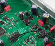
Update on the new ES9038Q2M DAC: Decided to find out if the sound quality problems mostly have to do with the switching power supplies. Tried running IV output stage and AVCC from LiFePO4 batteries. Better, but still not right and not close enough to right either. So... out come the caps and the opamps will be next. Will rebuild IV output to ESS recommendations and try again with batteries. Pics below for viewing enjoyment.
Note: the removed-parts-box is lined with anti-static foam. Keeps parts safe until i figure out what to do with them.
It seems that maybe there are different versions of this board, there are presentation pictures with different parts. Maybe the final product is being sold also with some lower cost parts. I will upload some of them in case you can recognize something useful. Some pages note about specifications:
(So it seems it is a bit different from the one that Markw4 has, different op-amps for example, some reference name codes, nobsound su5, d5, a20 ...? )
Details
① AKM professional digital receiver
- Adopt professional AKM digital receiver instead of the internal receiver of ES9038Q2M to achieve more natural sound of COAX / OPT input
- Adopt XILINX CPLD switch instead of the internal switch of ES9038Q2M
- Add digital shaping to optimize clock signal jitter, achieve better details and avoid switching POP sound
- XMOS XCORE2000 series module XU208
- Ÿ Adopt high-quality SPXO to achieve low jitter and phase noise
- Adopt widely recognized ESS SABRE series chip ES9038Q2M
- Extraordinary sound quality and super low distortion
- Support high specification DSD
- Adopt dual OP275G as I/V converter to provide high audio performance
- Adopt OPA2604 as LPF output to provide tube sound
- Adopt German WIMA and Japan Panasonic capacitors
- Specially designed analog circuit to achieve natural and enjoyable sound
- Adopt TI Hi-Fi headphone amplifier chip TPA6120A2
- Stable power supply and powerful drive suits for 16-300 Ω headphones
- Designed with headphone protection circuit
Parameters
- Dimensions: 150 (W) * 169 (L) * 44 (H) mm / 5.91 (W) * 6.65 (L) * 1.73 (H) in
- Package weight: 1.5 Kg
- Power port: DC 8-15V / > 1A (recommend 12V)
- Input: USB / COAX / OPT / Bluetooth
- Output: 2.0 stereo RCA / 3.5 mm headphone port
- USB input: PCM: 44.1-394 kHz / 16-32 Bit; DSD64-DSD256 / DOP / Native
- COAX / OPT: PCM: 44.1-192 kHz / 16-24 Bit; DSD64 / DOP
- Bluetooth input: Bluetooth 5.0 (Apt-X / Apt-X-HD)
- THD+N: < 0.0005% @ 1 kHz / < 0.0006% @ 20-20 kHz
- SNR: > 123 Db @ 1 kHz
- Frequency response: 20-20 kHz / ±0.35 dB
- Headphone amp power: 700 mw * 2 @ 32 Ω / 156 mw * 2 @ 300Ω
NEW Weiliang SU5 decoder ES9038Q2M chip XMOS 208 USB Multifunction Bluetooth 5.0 TPA6120 headphone supports DSD512-in Amplifier from Consumer Electronics on Aliexpress.com | Alibaba Group
TOP ES9038 Q2M DAC Decoder With XMOS XU208 USB Bluetooth 5.0 TPA6120 Headphone Amplier Support 32Bit / 384K DSD -in Headphone Amplifier from Consumer Electronics on Aliexpress.com | Alibaba Group
https://www.aliexpress.com/item/NEW-SU5-decoder-ES9038Q2M-chip-XMOS-U208-USB-Multifunction-Bluetooth-5-0-TPA6120-headphone-supports-DSD512/32883569560.html
Attachments
Last edited:
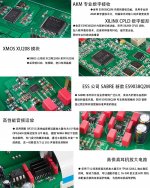
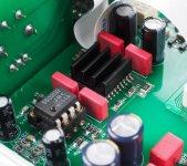
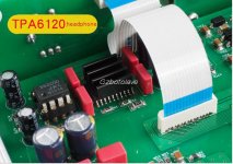
@pentajazz, Looks like there are two versions of the main PCB shown in the pictures. They vary in only one area, the headphone amplifier. The one I have here has a TPA6120A2 headphone amp which is preceded by a soldered-in opamp.
In the pictures that look different, the HPA chip looks like it has a heat sink stuck to it where is says 'Gzbotolave,' (in the pic below) and the opamp next to it is in a socket. The opamp that is soldered onto my board there is an OP275.
Otherwise, I see you have posted pics of various locations inside the unit, but they all like like mine does in those areas.
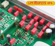
What they are calling the LPF is what I would call the differential output. Mine has an OP275 there. Easy enough to change that one thing.
Lastly, decided to double check, this is the one I ordered: GAO su5 ES9038Q2M DAC Supports input Bluetooth 5.0 APT X USB XMOS 208 fiber coaxial highest audio decoding 32 bit/384kHz DSD256 -in Digital-to-Analog Converter from Consumer Electronics on Aliexpress.com | Alibaba Group
The pictures of it show it has the HPA opamp in a socket even though the unit I received does not have the socket.
Thus my final conclusion is that there is probably only one version shipping. The one with a socketed HPA opamp may have been a prototype or something.
In the pictures that look different, the HPA chip looks like it has a heat sink stuck to it where is says 'Gzbotolave,' (in the pic below) and the opamp next to it is in a socket. The opamp that is soldered onto my board there is an OP275.
Otherwise, I see you have posted pics of various locations inside the unit, but they all like like mine does in those areas.
What they are calling the LPF is what I would call the differential output. Mine has an OP275 there. Easy enough to change that one thing.
Lastly, decided to double check, this is the one I ordered: GAO su5 ES9038Q2M DAC Supports input Bluetooth 5.0 APT X USB XMOS 208 fiber coaxial highest audio decoding 32 bit/384kHz DSD256 -in Digital-to-Analog Converter from Consumer Electronics on Aliexpress.com | Alibaba Group
The pictures of it show it has the HPA opamp in a socket even though the unit I received does not have the socket.
Thus my final conclusion is that there is probably only one version shipping. The one with a socketed HPA opamp may have been a prototype or something.
Attachments
Last edited:
One more thing about the new Chinese DAC unit and all the pictures, if you go back to the picture I posted here of my unit: http://www.diyaudio.com/forums/digital-line-level/314935-es9038q2m-board-158.html#post5473201
You can see I have labeled various sections of the circuitry. If you look at each one of the pictures in the ads for this unit, it is easy to identify which of the sections I have labeled is in each of the pictures.
You can see I have labeled various sections of the circuitry. If you look at each one of the pictures in the ads for this unit, it is easy to identify which of the sections I have labeled is in each of the pictures.
some differences from Markw4's board photo:
dip8 socket at headphone amplifier as noted (OP275 --> jrc 5532) (with different size red capacitors and black heat-sink)
op-amp 2x at I/V TL072 --> 2x OP275
op-amp 1x OP275 at diffout --> 1x OPA2604 (with different size red capacitors)
dip8 socket at headphone amplifier as noted (OP275 --> jrc 5532) (with different size red capacitors and black heat-sink)
op-amp 2x at I/V TL072 --> 2x OP275
op-amp 1x OP275 at diffout --> 1x OPA2604 (with different size red capacitors)
Last edited:
Here is a document from ESS describing the only opamps they have found to be acceptable for Sabre output stages, none of which are used with any versions of this DAC board. It also describes the requirements for AVCC power which the DAC board does not come close to meeting: http://www.esstech.com/files/4514/4095/4306/Application_Note_Component_Selection_and_PCB_Layout.pdf
In addition, the document describes the type of capacitors and resistors to be used with output stages to accurately reproduce DAC chip sound quality. This DAC board does not use the specified passive components, at least not for capacitors. Haven't checked the resistors yet. The requirement for an output stage ground plane is also not met.
As a result, it works but the sound quality suffers. It sounds a little better than the voltage mode DAC boards, but not close to my existing modded $39 Chinese DAC board. From my perspective it is a fix it or throw it away decision. I will give fixing it a try.
Last edited:
Markw4, your notes are useful! I guess there has to be extensive modification to achieve decent sound, personally I am not sure if I could follow those modifications, so maybe better off searching for tested/reviewed alternatives. At first glance it seemed that is a good design, maybe too much silicone for nothing...
Last edited:
- Home
- Source & Line
- Digital Line Level
- ES9038Q2M Board