Yeah AVCC does not like 12V one bit. It smokes on 12V.
Proving once again that smoke is what makes ICs work. Because they always stop working when you let the smoke out. 😉
. I was wondering why some designs were only capable of doing DSD 256 and some DSD512 with essentially the same chips....
Another reason could be related to minimizing jitter. As I mentioned previously the highest sample rate modes require the use of a 100MHz clock, but better jitter performance is possible with lower speed clocks. There is a design trade-off decision that has to be made.
In addition, TOSLINK is only good up to 96kHz, and SPDIF only good up to 192kHz. Higher speed modes require I2S audio which is usually done though a USB interface, and not all USB modules support the highest sample rate modes.
I think that we can learn a thing or two from the Pro-Ject "Pre Box S2 Digital" box. They gave pretty detailed description on the approach and the components used for headphone amp, power regulator etc.one can alway boost an op amp with a transistor or with an IC buffer. however I agree, it makes more sense to make a decent reg. at the moment for me the question still is monolith or discrete. LDO implementation appears not so simple at all. as discussed elsewhere, surrounding component type and quality may matter even more than their nominal values, and boost the price of such circuit significantly. the discrete reg appears to be more appropriate at the moment, but I think I have to find a better voltage reference than TL431 (which btw internally is a shunt regulator). and more importantly find out the best way how to minimise load transition effects on the reg. for the latest I need first to measure them, what is a task itself.
http://www.box-designs.com/inhalt/en/pdf/preboxs2digital.pdf
The power supply uses a LDO regulator ES9311 from ESS Technology.
http://www.esstech.com/files/3414/5193/1543/ES9311_product_brief_121715.pdf
Pro-Ject engineers are able to achieve the THD+N of -117dB with 600ohm loads headphone. It is pretty amazing for a $399 box. We are likely to spend more than that for our DIY project of ES9038Q2M box (or un-box).
Last edited:
...engineers are able to achieve the THD+N of -117dB with 600ohm loads headphone.
Perhaps good to bear in mind that THD+N is a pretty useless measure of performance although it is the most common metric commonly in use.
it is easy to measure, which may be why it became popular originally. At that time other measures were more difficult or impossible for many manufacturers.
For harmonic distortion it is important to separate out the percentages of individual harmonics, since the lower order harmonics are less objectionable and less audible than the higher order harmonics.
Also, good to recall that harmonic distortion is nonlinear distortion (measured at a given frequency such as 1kHz). Some audibly objectionable distortion may be classified as linear distortion (no new frequencies are created by linear distortion).
Some people may argue that nonlinear distortion is the only true distortion.
My opinion would be that any undesired alteration to a signal should be classified as noise or distortion. Noise is uncorrelated with the desired signal.
I would consider nonlinear distortion to include any undesired alterations to frequency response, time delays, volume levels, etc, that could not be classified as nonlinear distortion. As I mentioned previously, capacitor dielectric absorption that can be accurately modeled as equivalent to an RC ladder network would probably be classified as a type of linear distortion. In a DAC, audible reconstruction filter artifacts may include objectionable linear distortion of type known as Group Delay.
Given that there are numerous ways that audio may be undesirably and or objectionably altered, THD+N as a metric may be a little better than nothing, but a low THD+N number is no assurance of good sound qualtiy.
IIRC, Earl Geddes said something to the effect that THD is worse than no information at all because it can be misleading. It could lead someone to believe one product probably sounds a little better than another product when in reality the opposite could be true.
Last edited:
No informations about supply on the same pin from 2 sides.
Newermind...i go on with work. I will first try my previous combo as i tried with orignal board and listen then go further if any promising result will be hearable. Supply wil be 12V ACCU this will now feed 5 regulators.
Avcc is powered direct from Accu trought boosted lt3042. I left 4r7 to isolate regulator form 2x0.5F low esr caps( after testing i will deceide if any smaller caps will be needed for bypas, now is 3,3uf MKT and 0.1 PPS. I avoid ceramics near dac on analog lines. 5v preregulator for digital part is tps7a4700. I quick measured lines with scope, excellent, can*t see difference if i put scope probe on gnd or supply line. Extremelly clean.
Attachments

Last edited:
I think that we can learn a thing or two from the Pro-Ject "Pre Box S2 Digital" box. They gave pretty detailed description on the approach and the components used for headphone amp, power regulator etc.
http://www.box-designs.com/inhalt/en/pdf/preboxs2digital.pdf
The power supply uses a LDO regulator ES9311 from ESS Technology.
http://www.esstech.com/files/3414/5193/1543/ES9311_product_brief_121715.pdf
Pro-Ject engineers are able to achieve the THD+N of -117dB with 600ohm loads headphone. It is pretty amazing for a $399 box. We are likely to spend more than that for our DIY project of ES9038Q2M box (or un-box).
I own S2 box and regularly listen DSD128 content with Onkyo A800 headphones. It is designed by John Westlake ( John A. Westlake - Wikipedia ) and is a neat piece of engineering. It sounds good, and yes it can measure also pretty good upon certain setup. In a real life though, there is very little a diy-er can borrow from this design. This is a very compact and targeted design, capable to run from USB +5V or included basic SMPS. Linear PS or batteries may give better sound with it. So if one is looking for a relatively cheep, entry level HiFi DAC to enjoy the music, this is the thing. Unfortunately I still want to have some fun with prototype boards and soldering what will result in a ugly looking mess for sure. I know all this will cost me more than it is worth, but the time spent and lessons learnt are priceless. I just hope at the and of day The Sound also will visit me.
I quick measured lines with scope, excellent, can*t see difference if i put scope probe on gnd or supply line. Extremelly clean.
Did you measure on AVCC pins? At idle or playing something?
At idle and playing... tho one that stays as it was is 1,2V pin and DVCC that shows internal oscilator frequency. Analog lines are clean.
There is a 3.3V line in parallel with the line heading to the AVCC 3.3 V. We cut it to provide separated power to the "upper" power legs (DVDD, DVCC and VCCA). Between of two "isolated" VCCA legs we measured 5 ohm.
No informations about supply on the same pin from 2 sides. Newermind...i go on with work.
Very interesting and useful info. It is very similar in our case, finally we filtered the DVCC power line by 330 uF cap, and the soundstage increased as well. May be there are better methods to stop oscillation.
At idle and playing... tho one that stays as it was is 1,2V pin and DVCC that shows internal oscilator frequency. Analog lines are clean.
Last edited:
Thanks to clear this out! I was referring to the 100 ohm series, I was wondering whether or not it is in the useful range.
Regarding 100R on the output, I assume you are referring to a series resistor. Usually, a small series resistor on the output of an opamp driving an external output to a possibly unknown or incompletely defined load is a good idea. For one example, too much capacitance, say, from long cabling could potentially cause excess loop phase shift which could then result in opamp oscillation or other erroneous or sub-optimal circuit operation. Having some resistance in series with the output can help isolate the opamp from such effects.
so, upon the startup 3.3V LT3042 reg has to charge 0.5F through 4.7ohm resistor ? would not that result in 0.7A current, what would trigger over-current protection and shutdown-restart cycles?I left 4r7 to isolate regulator form 2x0.5F low esr caps
Ezitits... Thank you, i will measure what is startup current. Regulator is 1A. Any better idea, i will like to avoid direct connection to such a big capacitor?
Janos... fine that you also do in that way. So you bypassed pin 13 in the middle with 330uf
and you splitted 3,3v power lines. Now you power pin 27 with one regulator and pin 12 with another regulator. Yes you are right it is 5ohm between 2 pins?. Are regulator suitable for such paralel connection with just 5 ohm joined output?
I measured 1,2V voltage on 4r7resistor at startup and drops slowly..that is around 255ma...so arround 510ma on both channels.
Last edited:
Thanks to clear this out! I was referring to the 100 ohm series, I was wondering whether or not it is in the useful range.
Using 220R here, don't know about others.
May be there are better methods to stop oscillation.
We need to be clear on what we mean by oscillation, I think. If you see the clock frequency on a DAC pin, the only oscillation is in the clock, do we agree on that?
Maybe it will help if I try to explain what I mean:
To oscillate can mean to create a new frequency when there was none before, by either linear or nonlinear means. Usually (but not always), the word oscillator is reserved for a linear circuit using an (approximately) linear amplifier and just the right feedback to produce a sine wave.
Other circuits that generate new frequencies by other, nonlinear means may be referred to as waveform generators, multivibrators, etc. (Sometimes they are still called oscillators, it depends.) They typically use feedback with hysteresis and don't directly produce a low distortion sine wave.
A third way to produce a new waveform is by synthesis or arbitrary waveform generation, such as when a DAC is used to produce a sine wave. The DAC may be part of a frequency synthesizer, but I would not call it an oscillator exactly.
It is a very different thing when a frequency produced somewhere else and that is supposed to be somewhere else appears at a circuit node where it is not supposed to be. In that case the oscillation is not occurring at the node, so the node is not part of the oscillator.
In the case of the ES9038Q2M, if some oscillator frequency RF is seen on a power supply pin, it might be better to call it something like "20 millivolts peak to peak clock frequency RF," or something like that. Or maybe just, "some clock RF leakage." It depends on how much you know about what it is and why it is there.
Putting a bypass cap at the pin basically attenuates the voltage by letting some RF current flow into the cap and out to ground. Maybe some RF energy is dissipated in the cap ESR, otherwise it just circulates back somewhere through the ground plane. Bypassing the power pin does not stop the clock oscillator, it is still running fine, all that is changed is that the RF voltage on the power pin has been reduced in amplitude a lot.
Last edited:
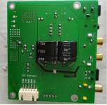
My es9038q2m board i2s input has a 5v input going into the dac chip. Right now I left it open, anyone knows what the is use of that input labelled v5.0?
Right now, I am modding my board to transformer output and will use a 10k:10K transformer connect directly to output pin with 680R direct across +/- output pin. The output is fairly low and I wonder if a higher value is better.
Right now, I am modding my board to transformer output and will use a 10k:10K transformer connect directly to output pin with 680R direct across +/- output pin. The output is fairly low and I wonder if a higher value is better.
Attachments
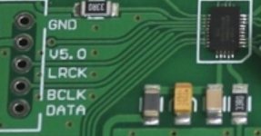

My es9038q2m board i2s input has a 5v input going into the dac chip. Right now I left it open, anyone knows what the is use of that input labelled v5.0?
Right now, I am modding my board to transformer output and will use a 10k:10K transformer connect directly to output pin with 680R direct across +/- output pin. The output is fairly low and I wonder if a higher value is better.
The 5v connection is the second from the top in the vertical column to the left. They didn't print the labels lined up very well. The 5v is a power output from the 5v regulator on the DAC board. It is there to provide power to an external I2S source device if it needs a power source. Otherwise it should be left disconnected.
If using a transformer output it is best to make the resistor as small as possible since DAC distortion is higher into a higher impedance load. The lowest distortion would be into an opamp IV stage.
When the DAC is operating into a higher impedance load such as one would get using a large resistor then the DAC would be operating in voltage mode which has rather poor distortion performance.
If using a current sense resistor such as is done when using transformer output, actually the transformer is not necessary for that to work. The voltage amplifier that connects to the transformer secondary could be connected directly to the sense resistor. The reasons for using a transformer rather than a direct connection include galvanic isolation and the addition of a little, possibly pleasant sounding transformer distortion. Some disadvantages of transformer output include relatively high cost and worse distortion performance than opamp IV output. One big attraction of transformer output is simplicity, it is easy to hook up.
Last edited:
- Home
- Source & Line
- Digital Line Level
- ES9038Q2M Board