Good question. But it is easy to use a transformer that has 2 secondary windings. The regulated DC output should be floating. Tight one low voltage with another high voltage to get the +/-.LT1083 is a positive regulator. How do they get -15v?
See the picture in this.
It would be great if I can convince you to test the ebay kit.
Last edited:
Two transformers are usually more expensive than one, and most power transformers don't have isolated secondary windings. Usually, its a single winding with or without center tap. You might get lucky though.
Power transformer with 2 or more separate windings are actually quite common. You can find them using "xxV + xxV" as search phase at any vendor's website or ebay. Two example are here.Two transformers are usually more expensive than one, and most power transformers don't have isolated secondary windings. Usually, its a single winding with or without center tap. You might get lucky though.
AS-1218 100VA 18V + 18V / 36Vct Audio Power Transformer | eBay
AS-1215 100VA 15V + 15V / 30Vct Audio Power Transformer | eBay
Center tapped transformer are common too. They should state xxVCT in their title. Separate windings can be wired as VCT so most manufacturer prefers to wind their product as separate windings and show them as either or.
They often do the same for the primary winding so that it can be either 110V or 220V input.
Last edited:
It would be great if I can convince you to test the ebay kit.
I am already using a linear supply with an LT1084 for the positive regulator, and it also has hexfred rectifiers in it.
I am thinking of trying some other less expensive fast turn-off, soft-recovery rectifiers to recommend instead instead of hexfreds. I do want to make sure transformer ringing is not a problem though. Sensitive audio circuits can the type where HF ringing may adversely affect sound quality.
How much trouble one needs to go to in order to control or eliminate ringing is another question. Snubbers can be quite effective and low cost but may require some trial and error to get right. They also might need help from better rectifiers anyway when the load may not be constant, or if not known in advance, say, maybe for something like a bench supply.
Although fancy rectifiers may cost more as opposed to snubbers, one can probably be more certain of getting acceptable results on the first try which may be preferred for a one-off DIY project.
How do you like its performance? Is it a built from scratch PSU or a commercial kit?I am already using a linear supply with an LT1084 for the positive regulator, and it also has hexfred rectifiers in it.
Wow, those transformers are pretty cheap and free shipping too. I guess the power supply you are considering might work okay. I would probably upgrade the rectifiers is all, maybe try something like these: VS-HFA04SD60STRHM3 Vishay Semiconductors | Mouser Or, these: STTH31AC06SPF STMicroelectronics | Mouser
However, with two separate power supplies using bridge rectifiers it can start to add up. Sometimes the cheapest solution doesn't end up being as cheap as it originally looked. 🙁
However, with two separate power supplies using bridge rectifiers it can start to add up. Sometimes the cheapest solution doesn't end up being as cheap as it originally looked. 🙁
How do you like its performance? Is it a built from scratch PSU or a commercial kit?
Performance is good. Not spectacular, but many things including most opamp circuits don't need spectacular. They do need good enough though.
It happens to be a kit I modified. No surprise coming from me I guess. Don't enjoy doing metalwork that much and I'm not really set up to do it well. Maybe that is part of the reason I don't enjoy it.

Last edited:
If I can get a package of 10 for $15/$16.6 from Mouser, it is not bad at all. In fact, quite reasonable. And I have 2 spares.Wow, those transformers are pretty cheap and free shipping too. I guess the power supply you are considering might work okay. I would probably upgrade the rectifiers is all, maybe try something like these: VS-HFA04SD60STRHM3 Vishay Semiconductors | Mouser Or, these: STTH31AC06SPF STMicroelectronics | Mouser
However, with two separate power supplies using bridge rectifiers it can start to add up. Sometimes the cheapest solution doesn't end up being as cheap as it originally looked. 🙁
On the other hand, the LDO regulator IC are more expensive. The kit I cited earlier (on order to me) uses UI620OG rectifier which I believe is a 3 terminal switching rectifier. Is switching rectifier good or bad for this application? Are they the same as fast recovery rectifier?
Last edited:
I would recommend this one PS ... HIFI DAC Power Board Fever DAC Power Supply Board +- 12V 5V replace LT1963AEQ | eBay
it has also +5V
it has also +5V
I would recommend this one PS ...
Don't see any snubbers, what are the rectifiers?
if I got the PCB correctly, then regulation is done by voltage reference (tl431 though), ne5534 error amp, IRF9Z34 pass MOSFET. kind of discrete LT1963 as they say ...
Hi
Actually the NewClassD (UWB) Regulator 15v Positive et -15v Negative
are very cheap .
NewClassD (UWB) Regulator 15v Positive 78xx Series
No preregulation:You just need the transfo (2x15v) , the rectifiers and capa.
You solder:
Directly the recifiers on the capa ( 10000µf ou more.... ) ,
The transfo on the rectifiers .
Two wires on the capa to the regulator.....
DIY😀
Serge
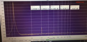
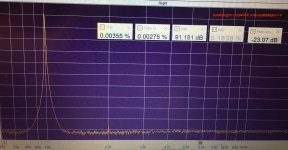
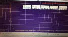
@eziitis, Hard to say what to try next for the remaining 2nd harmonic. .
yes, that second harmonic is present even more also in ProJect S2 digital, which I remeasured now. would it be an artifact of the measurement setup, but I doubt it.
anyway decided to go for the second approach with a different I/V. i have an ES9028q2m board which runs current mode and actually measures better than our es9038 board in stock. still a lot of 3rd and higher harmonics.
so I connected the DAC output of AVCC mod ES9038 board to the I/V stage on ES9028 board. the 2nd harmonic was still there, but a bit down. it disappears with AD797 op amp in the output filter. so perhaps resistor values are not optimal in this version of I/V. anyway sound is very good now.
btw changing onboard 3.3V reg to LT3045 does not improve the things, neither running it unbuffered for AVCC. this would mean that those e-bay boards with LT3042 regs still need op amp buffering ...
Attachments


Last edited:
eziitis, Looks like you are pretty serious about finding out for yourself what works and what doesn't. It is good to have someone here with us who is willing and able to try a lot of things and keep working on making progress.
In that regard, may I ask how close you may have come to trying just about the same as what I have done?
In that regard, may I ask how close you may have come to trying just about the same as what I have done?
I would recommend this one PS ... HIFI DAC Power Board Fever DAC Power Supply Board +- 12V 5V replace LT1963AEQ | eBay
it has also +5V
Are the IRF9Z34NS (?) in D2 pak (4 of them in each regulator board) the rectifiers?Don't see any snubbers, what are the rectifiers?
There are small 8-pin surface mounted device and a larger SOT223 style package. It is difficult to see what they are from the picture.
$23 for 3 separate regulator boards. A good deal if they are low noise. My concern is that the designer did not use any heat sink. I wish the seller would have post a schematic of the circuit.
Last edited:
Do you know the specification, such as current capacity, noise etc.?Hi
Actually the NewClassD (UWB) Regulator 15v Positive et -15v Negative
are very cheap .
NewClassD (UWB) Regulator 15v Positive 78xx Series
No preregulation:You just need the transfo (2x15v) , the rectifiers and capa.
You solder:
Directly the recifiers on the capa ( 10000µf ou more.... ) ,
The transfo on the rectifiers .
Two wires on the capa to the regulator.....
DIY😀
Serge
I suspect that they are directly replacement of the 78xx/79xx series. you can use any 78xx/79xx series board with them. But at $30 a pair, it is 30 time more than the classic LM78xx/79xx pair.
Last edited:
eziitis, Looks like you are pretty serious about finding out for yourself what works and what doesn't. It is good to have someone here with us who is willing and able to try a lot of things and keep working on making progress.
In that regard, may I ask how close you may have come to trying just about the same as what I have done?
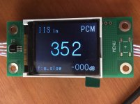
Thanks, Mark! the last iteration conceptionally seems to be similar to yours minus oscillator improvement and I am using I2S (the DAC will get the stream from RPI3). of course TH instead of SMD, different op amps and at the moment all this is just a quick prototype to see how the things work. anyway I can not measure more than about -100dB, so that perhaps is the limit for this case and I am not aiming to match a real HIFI leaving this for 2 other projects in parallel: es9028pro and AK4497.
to me the biggest difference appears how we get appropriate AVCC. yours use an integral LDO reg and an op amp buffer according to ESS design. I trust in simple series regs. they have low impedance over wide frequency range and importantly are good for loads with quickly changing current draw. I believe this technical diversity might be for common benefit.
So the current separate AVCC supply is fine for me in this case. for other consumers an integral reg(s) should be good enough. have to decide still which I/V version to use and what about the oscillator. next I have a temptation for a custom FIR filter. that would need an arduino hookup and finding out how to upload coefficients. at the moment I am not even sure that is possible on a mobile chip. but that most likely deserves another thread to discuss.
Custom coefficients are possible with mobile. However, I suspect it would do the most good if using SRC in which case a large transition band could be leveraged to minimize group delay and ripple in the audio band. Doubt anything could be done to prevent filter clipping though, probably need external DSP with more headroom to fix that. Also, if using internal filters only a couple of topologies to choose from, although maybe good enough in that respect. Otherwise, I doubt they didn't do what they could to optimize filter choices for use cases not changing the frequency landscape in ways such as can be done with pre-DAC upsampling.
It turns out SRC helps so much that if making a lot of DACs inclusion of a $15 SRC4392 chip could be easily justified. This is assuming other things like low-jitter clocking are addressed too.
EDIT: The SRC4392 boards I recommend have one I2S port. It is configured by the microcontroller as an input, I believe. You could use that input from RPI and output to the DAC using SPDIF for test purposes to see how you like it. Also, not hard to hack into the I2C bus to reconfigure the PCM/I2S port, I could even send you a hacked one to try. The SRC4392 also has a second such port but the IC pins are unconnected on the SRC board. Probably doable to attach leads there for testing and evaluation of simultaneous I2S I/O.
The point I want to make is that eventually somebody is probably going to figure out how to make a better sounding DAC than everybody else and it probably won't cost much more than the competing DACs. That better DAC will have to use SRC to be the best it can be, at least without full-blown external DSP in a SHARC chip which I don't expect to happen in that market.
Last edited:
To add a bit to my previous post regarding filters, it may be that they even anticipated there would be use cases where high sample rates were used with music recordings that did not actually have any frequency content above 20kHz. It may have been for that use case that they included the minimum-phase, slow-transition filter choice. I can't see anybody preferring it for 16/44 content since its side-effects are too audible in that case. However, the same side-effects are quite inaudible and the other, good qualities of the filter are evident when high sample rates are used and an empty transition band is available. That is to say, the filter sounds great (probably the most accurate of the filters) when playing CD audio through an SRC4392 (used for upsampling, and possibly for additional jitter reduction) before going into the DAC.
Last edited:
- Home
- Source & Line
- Digital Line Level
- ES9038Q2M Board