Would like to say something about I2S pin headers for the dac board. As I try to reduce DPLL bandwidth as much as possible in order to achieve best sound quality, there seems to be evidence that at the very low currents flowing through the I2S pins of the dac chip that nickel plated pin header connectors tend to easily become noisy and affect I2S signal quality. It appears they can cause increased jitter effects if the connection quality is not stable over time, which I am finding that it is not. In part, connection quality seems to be a function of connection contact force, but force from the small springiness in female electrical pin header connectors seems to relax enough to affect signal quality in as little as few hours or overnight.
As a result, I have ordered some gold flashed male and female pin connectors to replace the nickel plated I2S connectors in both of my modded dac boards. Would suggest others modding dacs also consider using gold flashed pin headers, or UFL connectors would probably work too.
The AK4137 board would need the same connectors as fitted to the dac board, or perhaps soldered connections. If not using ribbon cable, and using multiple separate wires of some type then probably best to try keeping them close together to help avoid noise pickup from loops.
Also good to keep the I2S wires as short as possible. The AK4137 and dac boards are not designed work with long transmission line interconnects.
Greetings.
Thank you Markw4 for the development of the theme.
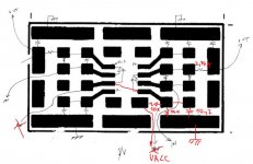
Ordered the DAC with aliexpress. While waiting for the parcel, I drew a power circuit for the digital part. Please suggest by the scheme.
Do you need diodes in the circuit?
Sorry for my english. I am writing through translate.google.
Thank you Markw4 for the development of the theme.
Ordered the DAC with aliexpress. While waiting for the parcel, I drew a power circuit for the digital part. Please suggest by the scheme.
Do you need diodes in the circuit?
Sorry for my english. I am writing through translate.google.
Attachments

Greetings.
Do you need diodes in the circuit?
Sorry for my english. I am writing through translate.google.
Hi dumohwow,
Not sure where in the circuit you may be thinking about additional diodes.
The Amanero does not need a power supply, as it receives power from USB.
I personally use one 5v LT3042 power supply that is shared by the dac board and the AK4137 board. However, it should be fine for each board to have its own 5v power supply.
What is important on the dac board is to add separate 3.3v regulators for the clock, and probably for VCCA. I happen to use LT1763 for those two. (The dac board comes with one 3.3v regulator that can still be used for the dac chip digital power and for the MCU.) The LT1763 clock and VCCA 3.3v regulators can be seen in the most recent pictures here: https://www.diyaudio.com/forums/digital-line-level/314935-es9038q2m-board-301.html#post5577671
The LTC6655 AVCC reference is also powered from the 5v dac board power supply.
In addition to the 5v supplies, you will also need high quality +-15v supplies for output stage opamps. The one I use has LM317/LM337 regulators for the 1st stage, then LT1963/LT3015 for the second stage.
Hopefully, the foregoing will answer your questions. If not, please reply and we can try to fill in any additional information that may be needed.
EDIT: I would like to add that for LT3042 or LT3045 regulators, it is a good idea to increase the Cset capacitor to the maximum value of 22uf. However, that will make start up rather slow. My AK4137 board will not boot if the +5v power comes up too slowly, so I modded the LT3042 board for fast start up as described here: ES9038Q2M Board - Page 154 - diyAudio
Last edited:
I have been following this thread with interest. Thanks.
Mark (and others) you may be interested in the ES9038Q2M DAC I spotted on Aliexpress recently -
Hi linuxfan,
By chance I ran across the post where I first received that dac. Don't know if you found it or not, but if still interested this is where the discussion of it starts: https://www.diyaudio.com/forums/digital-line-level/314935-es9038q2m-board-158.html#post5473107
@Markw4
You can better that noisy USB supply....
[DIY] TNT 221 USB Y-cable [English]
The Amanero does not need a power supply, as it receives power from USB
You can better that noisy USB supply....
[DIY] TNT 221 USB Y-cable [English]
DRONE7,
Agreed it is possible to power an Amanero board from other than USB. However, I have not found a clear need here.
It would probably help more to use an alternate power source, as suggested in the article, in the case of something like a USB powered dac, where all the analog circuitry is also running off USB power.
Last edited:
Thanks for the link Mark. Yes, read your observations about that DAC.
It's disappointing that what appears to be several respectable components can come together with such a mediocre final result.
It's disappointing that what appears to be several respectable components can come together with such a mediocre final result.
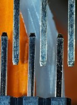
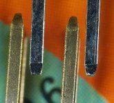
As recently described in an earlier post, due to problems with low level jitter caused by I2S connector noise on the dac board and AK4137 board, I ordered some gold flashed pin headers from a couple of places to try. I have some from JameCo and Digikey. The former supplied pin headers that look almost exactly like the nickel I had been having problems with. The latter source sent what I expected and will use.
Pics below both show nickel pins on top, and new pins on the bottom. The ones that actually look right are from Digikey. In sunlight, the JameCo pins do appear to have a very slight yellow tinge. Can't say there is no gold, but if any it must be very little.
Pics below both show nickel pins on top, and new pins on the bottom. The ones that actually look right are from Digikey. In sunlight, the JameCo pins do appear to have a very slight yellow tinge. Can't say there is no gold, but if any it must be very little.
Attachments
Last edited:
As recently described in an earlier post, due to problems with low level jitter caused by I2S connector noise on the dac board and AK4137 board, I ordered some gold flashed pin headers from a couple of places to try. I have some from JameCo and Digikey. The former supplied pin headers that look almost exactly like the nickel I had been having problems with. The latter source sent what I expected and will use.
Pics below both show nickel pins on top, and new pins on the bottom. The ones that actually look right are from Digikey. In sunlight, the JameCo pins do appear to have a very slight yellow tinge. Can't say there is no gold, but if any it must be very little.
It would be interesting to see a comparison of the 4137 vs Sabre's jitter rejection, both being ASRC's.
No info available WRT 4137, AKM application engineers didn't know what the CF was (LoL).
If you dig around here, there is actually a performance plot of the pre-Sabre,
ESS ASRC that Dustin was cooking up at the time. That part never saw the light of day but it's a fair assumption that it was the same ASRC that was integrated into the DAC.
I do remember it was extremely clean, also from memory, the jitter rejection corner freq, depending on settings, can go to at least as low as 0.1Hz.
I guess you know all that having signed the NDA 🙂 🙂
T
When it comes to a certain manufacturer's data sheets, the word 'sparse' may be a good fit. One may wish to adjust expectations accordingly.
Anyway, sound quality appears to be best when incoming jitter is already pretty low and settings are adjusted accordingly. It really does help to get in there and access registers, IMHO. And of course we are happy to be here and provide help and support as needed so everyone who wants to can be successful with all the modding.
Anyway, sound quality appears to be best when incoming jitter is already pretty low and settings are adjusted accordingly. It really does help to get in there and access registers, IMHO. And of course we are happy to be here and provide help and support as needed so everyone who wants to can be successful with all the modding.
We have had house guests here for the past week, so not a whole lot of progress locally. However, been doing some work to tidy up some loose ends on the existing dac project. Trying to reduce a little bit of power supply ripple showing up in the analog outputs. Also, replacing some problematic connectors. Now ready to do another experiment. Thinking of replacing one of the clocks on an AK4137 board with an low jitter NDK clock. Want to see if I can reduce DPLL bandwidth more if I can reduce phase noise in that area, which some previous experiments suggest might be possible.
While I am working on that here, just wondering if anyone out there working on a dac project has any progress to report? We sure like to hear any news that things are moving along, parts being ordered, clocks being swapped, whatever. Pictures are always welcome and appreciated. Good to see how things are coming along, and I think maybe it helps to keep the group focused on making progress if others are. There must be some out there with even a little progress? Thanks in advance for sharing!
While I am working on that here, just wondering if anyone out there working on a dac project has any progress to report? We sure like to hear any news that things are moving along, parts being ordered, clocks being swapped, whatever. Pictures are always welcome and appreciated. Good to see how things are coming along, and I think maybe it helps to keep the group focused on making progress if others are. There must be some out there with even a little progress? Thanks in advance for sharing!
Hi guys. Haven't been on here in a while as we had a death in the family. But last time I was here, a few of you had posted very lengthy advice for me which I am slowly getting through. I'd like to thank you all very much, particularly you Markw4.
Hi Alex,
Very sorry to hear about your loss. Hope the family is coping as well as possible with the situation.
Regarding the posted advice you mentioned, you are of course very welcome. Hope you find it meets your needs. If not, please let us know and we will be happy to answer any questions or fill in any gaps as best we can.
Regarding trial of an alternate clock for AK4137, I swapped in a little NDK 22.579MHz clock which was sold as a low jitter version. It is the oscillator that clocks the 11.2MHz DSD. Unfortunately, it made the DSD sound scratchy and more distorted. Looks like either the AK4137 board was manufactured with a very good clock to begin with, or the NDK clock is perhaps something of a dud. Waveforms look essentially the same on a scope, so no evidence of a problem there. Think I would like to try a Crystek in there, but it will take a few days to get one here. If it doesn't help then I will put back the original.
One of the things I noticed about the expensive and the low cost AK4137 boards is that both types have dedicated clock voltage regulators. Good thinking, whoever designed them. I find a dedicated clock voltage regulator helps with our dac project too. It is an easy way to get some extra sound quality improvement when doing a clock upgrade. Probably good to do the same thing for VCCA too.
One of the things I noticed about the expensive and the low cost AK4137 boards is that both types have dedicated clock voltage regulators. Good thinking, whoever designed them. I find a dedicated clock voltage regulator helps with our dac project too. It is an easy way to get some extra sound quality improvement when doing a clock upgrade. Probably good to do the same thing for VCCA too.
Last edited:
I would just remind folks that an SMD output stage board is kind of on the back burner for now, and it might stay that way somewhat indefinitely. It is just that right now I am mostly interested in thinking about and maybe investigating possible further sound quality improvements for the dac project.
In that context, and given it appears that we can at best find .1% tolerance SMD resistors to build with, making a different output stage layout as planned would not be expected to have much if any effect on dac performance. That being said, all the parts are here so its just a matter of doing the construction and documenting it. Also, I do want to get it done before too long in order to bring my 1st modded dac up to date in terms of sound quality.
However, if anyone else besides me wants to or has plans to use an SMD output stage and I am holding you up, or nearing holding you up, then please let me know and I will up the priority on getting that finished. I definitely do not want to deter anyone from working on their own dac modding project, so please do let me know your plans if they involve SMD output stage use and you know when you might be ready to work on that.
In other news, I see that Allo has started shipping Katana v1.2 dacs to some reviewers. Not me. Don't know if they still want me to do a review or not.
Moreover, don't know to what extent diyaudio member cdsgames is still in charge of the Katana project over at Allo. Kind of looks like he may have lost some power and prestige as a result of Katana 1.0 and 1.1 new product introduction complications. If so, that would be too bad. I think he was trying to do the right things.
In addition, it was quite unforeseeable that we would make the diy progress with ES9038Q2M that we have. When Katana was conceptualized and through most of its development, there was thought to be no Q2M dac that could compete on sound quality. Nobody could have known our modded dac would eventually turn out to be one of maybe two. The other is Ayre QX-8, priced at $4,950. My Quest for a new DAC, Part 2 - Ayre QX-8 - Reviews - Computer Audiophile
Hi Markw4
just ordered a 2nd es9038q2m board (green version) to modify as I am a little afraid of changing something on my current modded board and killing it with no back-up. I also see an option using this 2nd DAC board as DAC when doing digital XO filtering for my 2 way speakers in future (currently its analog active filtered).
Further I would like to have a comparison board to my current board to see if I can further improve SQ by different mods.
I want to do the smd output stage again, using modified onboard circuit as symmetry stage again.
I will use crystek clock this time (instead of NDK Sda), LTC6655 as ref for AVCC and 22uF MKP film caps for AVCC.
Clock, VCCA and DAC power will be filtered with LP5907 LDO, while I feed 5V to the orig. 3,3V powerlines (MCU line keeps orig. 3.3V reg). The 3,3V LDO will be placed where ferrite filters are applied at the moment.
So what I would like to know about your new smd version is, if you will do same circuit as for through hole or any other mods like rasmussen filter or other values for resistors or mlcc? Will you use AD797 this time? Do you have a part list already?
I would like to place europe mouser order within the next days.
Last edited:
Hi Freezebox,
I am using AD797 for AVCC. I have two of them on a single to dual plug in adapter so they can work with a dual opamp socket pattern. I found they get rather hot with two of them right together in a confined space, so stuck a heat sink on them which seems to take care of the heat well.
Regarding the so-called Rasmussen mod, I am not seeing a need for that although you could experiment with one if you like. I did think about it quite a bit, but I am finding that distortion is very low, and I can't attribute remaining limitations of sound quality to RF coming out of the dac when using the new output stage. However, I twisted the dac analog output wires together and ran them right next to the ground plane going out to the output stage board. Could be there is a few pf of filtering that way. If so, it seems like probably enough for now.
Regarding continued tweaking of things we are already doing pretty well, I am making one exception trying to reduce jitter coming out of AK4137 board. That turns out to be pretty tricky and in the end it may be best to hard solder the I2S connections with very short length ribbon cable. However, the effects are only noticeable if trying to reduce DPLL bandwidth to the minimum. Just closing the lid on the steel server case can make a small difference, which says to me that the EM fields are not well enough contained given the design of the dac and AK4137 boards and how they get wired together. A very few pf at 11.2MHz and or most likely its higher harmonics has an effect which is not always perfectly stable. Probably better to have the Q2M and the AK4137 on the same multi-layer PCB. Since we don't have that, we have a little more a a challenge to make it work as well as possible. Again, nobody will notice this unless trying to tweak DPLL to the very fullest extent (which is what I would like to be able to do 🙂 )
Regarding Rasmussen mod and Katana dac, it may help more in that case since they are using discrete transistors to make opamps which cannot operate at frequencies nearly as high as LME49720 can. In that case, RF is more likely to cause distortion problems, IMHO.
It could also be that if we ever get Spartan 6 DSP and clocking to an optimal point, we might find that coming back and doing some kind of post dac but pre I/V filtering could make a small beneficial difference. For now, at least with the twisted wires, I don't think we are at a point where it matters.
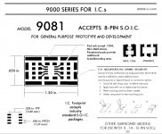
Regarding a BOM, I ordered most of the SMD parts in one Mouser order, so I could give you the part numbers. They are all 805 size parts, the smallest that work with Surfboards. All values are the same as for the through hole output stage. Resistors are Vishay, and caps are C0G, except for power supply bypass caps which are tantalum and X7R. If you want to use 805 size parts, I would be happy to give you part numbers. If you want bigger, such as 1206, then you would have to look up the part numbers yourself, but it is easy enough to do.
I did a rough sketch of how to layout all the parts on three Surfboards, two of them to mount the I/V stages and a couple of the RC filter parts that start the differential summing and filtering stage. The 3rd board would contain the remainder of the differential summing and filtering for both channels. Fitting all the parts on 3 Surfboards is not hard, but it would involve cutting and subdividing some longer length solder pads on the boards as described in the Surfboard data sheets. I guess try could photocopying my layout sketches, or better yet redraw them more legibly. Let me know if you want me to do that which I expect to you will and that's fine, just if you don't want me to I can be lazy and not do it yet.
Most likely the 3rd Surfboard could be omitted and the existing output stage traces on the dac board reused, as you suggest. In that case, the I/V Surfboards might fit on the bottom of the dac board, but it could be a tight fit. Maybe better to put them on another board, and then attach that board to the bottom of the dac board, carefully bonding the ground planes of the two.
Okay, enough typing for now. I will take a break and await your reply. Let me know what you would like from me so you can get to work on SMD and then I will see what I can do to get going on that.
I am using AD797 for AVCC. I have two of them on a single to dual plug in adapter so they can work with a dual opamp socket pattern. I found they get rather hot with two of them right together in a confined space, so stuck a heat sink on them which seems to take care of the heat well.
Regarding the so-called Rasmussen mod, I am not seeing a need for that although you could experiment with one if you like. I did think about it quite a bit, but I am finding that distortion is very low, and I can't attribute remaining limitations of sound quality to RF coming out of the dac when using the new output stage. However, I twisted the dac analog output wires together and ran them right next to the ground plane going out to the output stage board. Could be there is a few pf of filtering that way. If so, it seems like probably enough for now.
Regarding continued tweaking of things we are already doing pretty well, I am making one exception trying to reduce jitter coming out of AK4137 board. That turns out to be pretty tricky and in the end it may be best to hard solder the I2S connections with very short length ribbon cable. However, the effects are only noticeable if trying to reduce DPLL bandwidth to the minimum. Just closing the lid on the steel server case can make a small difference, which says to me that the EM fields are not well enough contained given the design of the dac and AK4137 boards and how they get wired together. A very few pf at 11.2MHz and or most likely its higher harmonics has an effect which is not always perfectly stable. Probably better to have the Q2M and the AK4137 on the same multi-layer PCB. Since we don't have that, we have a little more a a challenge to make it work as well as possible. Again, nobody will notice this unless trying to tweak DPLL to the very fullest extent (which is what I would like to be able to do 🙂 )
Regarding Rasmussen mod and Katana dac, it may help more in that case since they are using discrete transistors to make opamps which cannot operate at frequencies nearly as high as LME49720 can. In that case, RF is more likely to cause distortion problems, IMHO.
It could also be that if we ever get Spartan 6 DSP and clocking to an optimal point, we might find that coming back and doing some kind of post dac but pre I/V filtering could make a small beneficial difference. For now, at least with the twisted wires, I don't think we are at a point where it matters.
Regarding a BOM, I ordered most of the SMD parts in one Mouser order, so I could give you the part numbers. They are all 805 size parts, the smallest that work with Surfboards. All values are the same as for the through hole output stage. Resistors are Vishay, and caps are C0G, except for power supply bypass caps which are tantalum and X7R. If you want to use 805 size parts, I would be happy to give you part numbers. If you want bigger, such as 1206, then you would have to look up the part numbers yourself, but it is easy enough to do.
I did a rough sketch of how to layout all the parts on three Surfboards, two of them to mount the I/V stages and a couple of the RC filter parts that start the differential summing and filtering stage. The 3rd board would contain the remainder of the differential summing and filtering for both channels. Fitting all the parts on 3 Surfboards is not hard, but it would involve cutting and subdividing some longer length solder pads on the boards as described in the Surfboard data sheets. I guess try could photocopying my layout sketches, or better yet redraw them more legibly. Let me know if you want me to do that which I expect to you will and that's fine, just if you don't want me to I can be lazy and not do it yet.
Most likely the 3rd Surfboard could be omitted and the existing output stage traces on the dac board reused, as you suggest. In that case, the I/V Surfboards might fit on the bottom of the dac board, but it could be a tight fit. Maybe better to put them on another board, and then attach that board to the bottom of the dac board, carefully bonding the ground planes of the two.
Okay, enough typing for now. I will take a break and await your reply. Let me know what you would like from me so you can get to work on SMD and then I will see what I can do to get going on that.
Last edited:
@Freezebox,
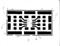
Made a quickie SMD I/V layout w/RC output filter which would then go to the rest of the differential summing stage. If you want to reuse the existing traces on the top of the dac board for that, that should be fine. Maybe you could post the layout for that part in case anyone else is interested? 🙂
EDIT: I would suggest using copper foil to connect the ground pads to a ground plane on the underlying board the Surfboard is mounted on.
Attachments
Last edited:
Hi Markw4,
thank you for your draft and comments. I will post my design differential when new board arrived and components are unsoldered..Would there be an disadvantage in adding voltage devider for Vref to the i/v board as below (red lines), such as e.g. longer wire with AVCC might grab more RF BEFORE devider (but 10uF cap closer to Vref input at i/v opamp..)?
Why dont you add a resistor in series to the 330pf cap (both in parallel to the i/v 820 R) as ESS recommends? Wouldn´t this improve RF filtering on i/v stage?
Attachments
- Home
- Source & Line
- Digital Line Level
- ES9038Q2M Board