HUD-mx2 vs. ES9038q2m
Now the first sound check is done. The HUD (is the winner) against the unmoded green board . The HUD has much more power and more clarity and 3d structure. So I will do mod by mod until the HUD will be beaten 🙂
For the i2s source, I have a BT csr8675 and a USB xmos208. The board for an electronical switch is on the way.
My sound chain after the DAC is a tube buffer (modded with mundorf caps and svetlana tubes) and then a TPA3255 EVM (or a JLH Class A) and the speakers are Magnat.
My sound chain after the DAC is a tube buffer (modded with mundorf caps and svetlana tubes) and then a TPA3255 EVM (or a JLH Class A) and the speakers are Magnat.
Woah! Here is a man who could use a modded LME49600 headphone amp. 🙂
Actually, everyone should have a least one ultra low distortion power amp of some kind. An HPA can work sufficiently for that use at pretty low cost. There has to be some good way to hear your dac accurately, and so that you can have something to help calibrate your ears to the sound coloration of your big system (if you have one). Otherwise, it can be very hard to know if you are missing something or whatever else. That happened to me with my old Bryston 4B power amp. Very well known and with a good reputation in its day, it could not reproduce everything my dacs were able to play. Sound details were just missing and or distorted.
Shall a very accurate and quite low cost HPA be our next group project to work on including instructions, schematic, layout drawing, and BOM? It is well worth the effort, IMHO.
Other than that, please tell me what is a HUD?
HD Compensation Notch Filter and Parts Therefor
Okay, great. However, I hope you didn't mean you would only mod until HUD is beaten. That might not take too much. It is important to do as many of the mods as possible if you want to have a really good dac that will stand the test of time for several years.
Where maybe it could get to be a problem for some people would be when it comes to doing harmonic distortion compensation, as it would be pretty unusual to be able to do it without an active, say, 1kHz, notch filter.
That is because most sound cards don't have clean enough A/D not to add significant distortion of their own without notching out the highest level signal, which we usually select to be 1kHz.
When we get to that part, people not presently equipped with a notch filter, or who can't borrow one, would be faced with a choice of making one or skipping the harmonic compensation capability.
I guess we can take that on when we get closer to needing it, unless people who want to order parts only once want to order parts now for that too. If there is anyone in that position, or who would like to know more about what HD compensation does for sound quality before deciding, we can talk about it now or at any time.
If anyone would like to have it, I could make up a parts list for the filter which would only include a few more opamps, resistors, caps, and trim pots. Well, maybe SMD adapters too for the opamps, although they can probably be ordered already mounted to adapters from an adapter company.
Also, if anyone would like to see what a filter build looks like I could post a pic, so people could see how much work it looks like.
The good thing about it would be once one has a notch filter, it could be used for lots of things such as preamps, power amps, etc. Also, the way I did the layout for mine uses a little plugin for frequency selection components. That way the same filter board could be used for, say, 100Hz, or 10kHz. Just swap out the plugin to change the notch frequency. Very handy test device to have for an audio hobbyist.
...I will do mod by mod until the HUD will be beaten 🙂
Okay, great. However, I hope you didn't mean you would only mod until HUD is beaten. That might not take too much. It is important to do as many of the mods as possible if you want to have a really good dac that will stand the test of time for several years.
Where maybe it could get to be a problem for some people would be when it comes to doing harmonic distortion compensation, as it would be pretty unusual to be able to do it without an active, say, 1kHz, notch filter.
That is because most sound cards don't have clean enough A/D not to add significant distortion of their own without notching out the highest level signal, which we usually select to be 1kHz.
When we get to that part, people not presently equipped with a notch filter, or who can't borrow one, would be faced with a choice of making one or skipping the harmonic compensation capability.
I guess we can take that on when we get closer to needing it, unless people who want to order parts only once want to order parts now for that too. If there is anyone in that position, or who would like to know more about what HD compensation does for sound quality before deciding, we can talk about it now or at any time.
If anyone would like to have it, I could make up a parts list for the filter which would only include a few more opamps, resistors, caps, and trim pots. Well, maybe SMD adapters too for the opamps, although they can probably be ordered already mounted to adapters from an adapter company.
Also, if anyone would like to see what a filter build looks like I could post a pic, so people could see how much work it looks like.
The good thing about it would be once one has a notch filter, it could be used for lots of things such as preamps, power amps, etc. Also, the way I did the layout for mine uses a little plugin for frequency selection components. That way the same filter board could be used for, say, 100Hz, or 10kHz. Just swap out the plugin to change the notch frequency. Very handy test device to have for an audio hobbyist.
Last edited:
As this thread has almost reached 300 pages:
Could anyone do a roundup?
Can the DAC run in current output and how?
All the best,
Salar
Could anyone do a roundup?
Can the DAC run in current output and how?
All the best,
Salar
Hi Salar,
Welcome to the thread. Attached is the latest updated list of posts that I keep for my own reference.
Maybe the most useful post to start with is this one which shows some pictures of the 1st dac I modded at the beginning and most recently: https://www.diyaudio.com/forums/digital-line-level/314935-es9038q2m-board-280.html#post5557498
Right now, due to popular request, we have come up with two major mods that don't require using SMD components. Don't know if you are comfortable with SMD work or not. There is an output stage board that attaches to the dac board. The new output stage has a schematic with more analog filtering than we used the first time around, and it uses through-hole components rather than SMD. The other new mod version is a through-hole component (mostly) version of an AVCC board. AVCC in case you don't know is super critical analog reference voltage used to generate the audio output of the dac.
What determines whether Sabre dacs run in current mode or voltage mode output is the input loading of the output stage. If it bridges the dac outputs with a high-Z load, then the dac is said to be operating in voltage mode. If the the input to the output stage is sort of a virtual ground offset to one-half of the AVCC voltage, then the dac is operating in current mode. The voltage that is one-half of AVCC, or AVCC/2 is also referred to as Vref.
EDIT: There are separate AVCC and Vref voltages for each dac channel.
The dac uses differential outputs, two per dac channel. They must be converted to voltages by I/V converters offset to Vref, then the voltages are differentially summed to give an analog audio output for each channel. The output stage does analog filtering at the same time as doing its other functions.
The mods to the dac board include the two boards mentioned above, a new ultra-low jitter clock, connections to I2C bus for accessing dac chip control registers, external power supplies, local regulators for the clock and a voltage called VCCA, and an external AK4137 board of some type for upsampling and conversion of PCM inputs to 11.2MHz DSD, which we have found sounds best for the dac chip as operated in our modded environment.
Also recommended by me are to build a low-cost modded LME49600 headphone amp, and for those that don't already have one, a notch filter to assist with harmonic distortion compensation adjustments.
It is also recommended to study the materials at the ESS Tech website downloads page. You may also want to contact the ESS distributor for your locale to request and NDA (non-disclosure agreement) form that you can fill out if you would like a data sheet for the ES9038Q2M dac chip we use. One of the hassles of using Sabre dacs is that ESS apparently tries to keep competitors from copying its intellectual property by keeping data sheets as trade secrets. Maybe it helps prevent cloning of chips, I don't know exactly.
You might also want to watch some videos on youtube of Martin Mallinson talking about Sabre dac technology. There are only a couple, but they are one way to learn more about the architecture.
After you have had a chance to look around a little, if you have any specific questions please let me know.
You can also let us know if you have any trouble getting an NDA form from your ESS distributor if in fact you decide to request one.
Again, welcome to the group and hope you find the dac modding experience very rewarding. You will end up with an excellent dac if you follow through with all the mods. So far as I know there is only one ES9038Q2M dac with better sound quality than our modded one, and it cost almost $5,000 including the USB input option.
Attachments
Last edited:
Hi Markw4,
thanks a lot! Any schematics on the mod?
About NDA: Current output should not be touched by this-
and any owner of the board can easily figure ot the important connections.
Maybe I can do it another way:
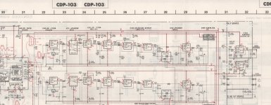
I want to use the board in an old CDP-103:
With the help of the forum, I got experience in profiding SPDIF-Out in old
2nd generation Sony chipsets:
How to get your beloved CD-player from the eighties into the Digital Domain
So I could use the original output stage:
Give it it´s own supply, disconnect it´s ground, bypass Emphasis and Mute etc. It "only" has to be adapted to the ES9038Q2M output...
All the best and thanks,
Salar
thanks a lot! Any schematics on the mod?
About NDA: Current output should not be touched by this-
and any owner of the board can easily figure ot the important connections.
Maybe I can do it another way:
I want to use the board in an old CDP-103:
With the help of the forum, I got experience in profiding SPDIF-Out in old
2nd generation Sony chipsets:
How to get your beloved CD-player from the eighties into the Digital Domain
So I could use the original output stage:
Give it it´s own supply, disconnect it´s ground, bypass Emphasis and Mute etc. It "only" has to be adapted to the ES9038Q2M output...
All the best and thanks,
Salar
Attachments
Hi Salar,
The dac chip has built-in support for CD de-emphasis, etc. Best to wrap this dac chip in the circuitry it needs to perform well rather than try to mate it to circuity for a very different kind of chip.
If you can provide SPDIF input or I2C, PCM, etc., any of those would be fine. You should then connect the output of our output stage to the audio out terminals on your CD player. Otherwise, you will probably get lousy performance and waste your time and mine.
These Sabre dacs output low level RF and have other quirks that require very particular circuitry tailored to the narrow window of what works for them.
If you would be willing to use our mods and skip circuits in the Sony player that are not suited to this type of dac chip then you might be able to make it work. Otherwise, you might want to keep looking for some other kind of dac chip that is more well suited to what you want to do.
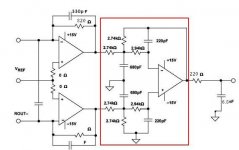
EDIT: I will post the output stage schematic. It is for one channel only and doesn't show decoupling. Vref comes from the AVCC board. Opamps are LME49720.
Also, I would recommend you study this very carefully: http://www.esstech.com/files/4514/4095/4306/Application_Note_Component_Selection_and_PCB_Layout.pdf It talks about component selection and ground plane continuity to output stage, etc.
The dac chip has built-in support for CD de-emphasis, etc. Best to wrap this dac chip in the circuitry it needs to perform well rather than try to mate it to circuity for a very different kind of chip.
If you can provide SPDIF input or I2C, PCM, etc., any of those would be fine. You should then connect the output of our output stage to the audio out terminals on your CD player. Otherwise, you will probably get lousy performance and waste your time and mine.
These Sabre dacs output low level RF and have other quirks that require very particular circuitry tailored to the narrow window of what works for them.
If you would be willing to use our mods and skip circuits in the Sony player that are not suited to this type of dac chip then you might be able to make it work. Otherwise, you might want to keep looking for some other kind of dac chip that is more well suited to what you want to do.
EDIT: I will post the output stage schematic. It is for one channel only and doesn't show decoupling. Vref comes from the AVCC board. Opamps are LME49720.
Also, I would recommend you study this very carefully: http://www.esstech.com/files/4514/4095/4306/Application_Note_Component_Selection_and_PCB_Layout.pdf It talks about component selection and ground plane continuity to output stage, etc.
Attachments
Last edited:
Thanks! As output stages looked almost the same in the good old times with R2R Dacs,
I thought this idea would be a nice try.
Questions about your output stage:
Rout- is connected, VRef is 3.3V, where is the positive differential output?
The unnamed connection on the upper left side..?
I assume the red-squared area is your additional board, whreas the left side is
the modified circuitry of the original board? Which opamp did you use?
All the best,
Salar
If you go to the page you already found before there is a pinout of the dac chip. It has two differential outputs per channel. https://www.diyaudio.com/forums/digital-line-level/314935-es9038q2m-board-240.html#post5526080
They are DACR and DACL for right and left. The inverted differential outputs are labeled the same, but with a B suffix.
Vref is approximately +1.65v =AVCC/2 and it should be derived from AVCC for each channel.
An AVCC schematic is listed in the post list I already gave you: https://www.diyaudio.com/forums/digital-line-level/314935-es9038q2m-board-271.html#post5546958
Another version is attached below.
If you are too excited to take the time to read and study, then all the more important that you follow our mods exactly as instructed and shown in pictures, etc. Otherwise, you are most likely going to be very disappointed.
Attachments

Last edited:
Hi Mark,
thanks a lot for your reply.
Well, I have a very time consuming job - even on Sundays - so it is not a matter of excitment but just time. Time to rebuild the mods -yes. To gather all background information -no.
So I assume that in your schematics in post #2948 Rout+(DACR) was not labeled and it is the connection on the upper left, correct?
The red squared area ist the additional board, correct?
As far as I understand, the output stage mod can be done without an additional board using SMD components (which I can handle) -correct?
Is the AVCC board also needed with a clean, low noise power source?
Is there somewhere in this thread the schematics of the unmodiefied board to understand the differences?
Thanks a lot for your kind help,
Salar
Hi Salar,
There are two dac outputs per channel and two inputs per channel for the output stage. So long as both channels are wired consistently, it isn't critical which one is the inverted and non-inverted outputs. The important thing is that both channels are in phase with each other. The output stage board ground plane needs to be part of the dac board ground plane.
The area circled in red is the part that is a multi-feedback filter architecture, that's all.
The AVCC board opamps run on the same +-15v power as the output stage opamps. The LTC6655 runs on clean 5v. There is no substitute for the AVCC board, it is critical and it is required. It is also critical that the output pins of the AVCC board be located right at the input pins of the dac chip, and that the its ground plane be part of the dac board ground plane.
There is no full schematic of an unmodded board that I am aware of. Once you get your's it is easy enough to trace out if you want.
You can build with SMD parts if you want. Use good quality thin film resistors in 0.1% tolerance or better, and C0G or NPO caps only, except use 10uf tantalum and .1uf X7R ceramic in parallel for decoupling at each opamp power pin. However, unless you are very experienced at laying out high performance circuitry, I would recommend you follow the established and tested layouts.
You don't seem to be aware of how difficult it is to build something with very low distortion down at -120dB. It is not a trivial undertaking. Are you sure you really need a dac of this quality? It is a lot of work to get it right.
Last edited:
Hey Salar,
Tell you what, I am starting to have a very bad feeling about you getting though this the way the rest of the group is doing. You seem way too new at this. I may have a good option for your though. There are some mods for this board by a guy named Victor who is a very good designer and who did not want to go to as much trouble as we do here for a semi-perfect dac. Victor has some mods for this dac that are much easier to do and that measure very well if one can accept what I would consider to be a lesser result. It would still be a lot better than the stock dac board you will receive. Does that seem like something that might interest you?
Tell you what, I am starting to have a very bad feeling about you getting though this the way the rest of the group is doing. You seem way too new at this. I may have a good option for your though. There are some mods for this board by a guy named Victor who is a very good designer and who did not want to go to as much trouble as we do here for a semi-perfect dac. Victor has some mods for this dac that are much easier to do and that measure very well if one can accept what I would consider to be a lesser result. It would still be a lot better than the stock dac board you will receive. Does that seem like something that might interest you?
Han Solo had a bad feeling. What´s the point? This thread was a work of progress and is almost done.
In this forum I do share my little kowledge as far as I can to others (like aligning vintage CD-Players)
In this thread not have the time to read through 300 pages / 2953 posts and filter out the information.
Thus the original unmodded schematics of the board (maybe hidden in this thread, maybe published by me one day)
would be useful, as well as the schematics of the mods - on one page.
Asking whether DACR was omitted or simply forgotten comes from my
experience with balanced output stages. So I am not as new as you might expect.
Again, this roundup would help other people as well...
Okay, then. Just checking.
Reason there is not as much of a roundup as might be nice is exactly because it is a work in progress. And, I only volunteer to do work that I feel like doing myself. If you would like to contribute back by volunteering to help with a roundup, no doubt it would be appreciated by the next people that may come along. Thanks in advance for any help with the project you are able to do! 🙂
If you want to reduce the physical size of the finished board you will have, I would suggest doing AVCC as can be seen in recent pictures of the bottom of my first dac board. It is still the same schematic as we are using now. Main difference is that the LTC6655 output cap is ceramic rather than film, but it works well enough I won't change it. I just made it very small with SMD parts mounted unconventionally. Happy to talk to you about doing the same if you want to try it.
Regarding an SMD output stage, I have parts on hand to lay out one when I have time. It should have about the same area as the through hole component output stage, but it will be much thinner as the SMD parts will be laying flat. By the time your dac board gets here from China there is a good chance I will have something ready to show on that. If not, maybe we can work on it together. If you want to make the whole assembly smaller, you could try sliding the output stage board up more towards the dac chip before attaching to the dac board ground plane. Might be more practical to try that with an SMD output stage.
Also, don't know if you are aware or not, but many of the pictures I post are hi-res so you can see details of construction. It isn't always obvious how to get pictures to show at full size, which is done by opening them then clicking on the white X in the lower left corner (if present).
Last edited:
Looks like through-hole-component project dac is about done. I have to finish inspecting and ringing it out. Then I will do some initial power on testing, maybe tomorrow. If everything seems to be working okay, then it will go into the test system case for initial listening tests, including comparison with the other reference dacs here. If all is good, then I will get set up to adjust harmonic distortion compensation. The numbers that come out of that should give a rough idea as to how linear the new AVCC and output stage boards are as compared to the 1st modded Q2M dac.
Be interesting to see how this one turns out. Of course, hoping it is at least a little better than the 1st board including with the ad hoc additional output stage analog filtering I did for it last time. We'll see pretty soon.
Be interesting to see how this one turns out. Of course, hoping it is at least a little better than the 1st board including with the ad hoc additional output stage analog filtering I did for it last time. We'll see pretty soon.
New board is up and working on the bench with a test power supply. AD797's on dual adapter is handling AVCC fine. Tomorrow the new dac will go in the test box where I can hook up the AK4137 and playback through the power amp and speakers. We'll see how it sounds then.
Okay, we're up and running on the speakers. Just compared sound with Katana 1.1
If anything I feel a little bad that the new modded version is clearly superior. I sure hope Katana 1.2 brings it back into the running, which is something people not into modding need to be to access at an affordable price (even though it is limited to RPi music playing).
I think this latest version of mods is another improvement over my last mods of the 1st dac. Probably (within a gnat's hair) as good as we can get without external interpolation filtering, and it is very good indeed. If we ever get around to doing external filtering later it would just be an add-on to this dac, no rewiring required. So, I say go for it. It sounds good and you will be happy, and this is without even getting to harmonic distortion compensation and DPLL bandwidth yet.
Time to get those parts orders in, I would say.
I should probably also mention that I decided to reinforce the mounting of the AVCC board with a little bit of green epoxy putty. With just solder holding along that small strip of ground plane, it could be tipped a little and it would stay wherever it was tipped to. I am talking only a very few degrees of tipping angle from inadvertently pushing on it a little while working on other things, but too much of that and something would eventually fatigue to a breaking point. So, epoxy putty is the fix for mechanical stability here.
- Home
- Source & Line
- Digital Line Level
- ES9038Q2M Board