Due to the shape of my room, I need to equalize one speaker channel. I need to drop 5db at 70hz. I came to this conclusion by experimenting with EQ. But I don't want to use EQ so looking for a better way to equalize the speaker line it's self, since it's only one narrow frequency drop.
In preamps this can be done with capacitor values but what about directly on speaker wire handling 50W? Is there some other option? I don't want to run my signal through another preamp like EQ as this degrades the signal so that's why I'm asking.
In preamps this can be done with capacitor values but what about directly on speaker wire handling 50W? Is there some other option? I don't want to run my signal through another preamp like EQ as this degrades the signal so that's why I'm asking.
Trust me on this one ... building a notch filter into your speaker's crossover is going to degrade the signal a lot more than tweaking it with an EQ.
Plus it has the added disadvantage that it cannot be adjusted or undone.
Then there's the matter that 5db is almost nothing given the often wild variations in rooms and speaker to start with. I'd bet you couldn't even hear it.
Plus it has the added disadvantage that it cannot be adjusted or undone.
Then there's the matter that 5db is almost nothing given the often wild variations in rooms and speaker to start with. I'd bet you couldn't even hear it.
Last edited:
I guess you right, it's not worth it. There is an option that if I move the speaker to another position,it's better. Only reason I didn't do this obvious cure is because I have something else in that spot, maybe time to rearrange the room a bit.
What would happen?building a notch filter into your speaker's crossover is going to degrade the signal a lot more than tweaking it with an EQ.
What would happen?
Two things are likely ... First the filter in the crossover would have a lower Q than one at line level or in the digital domain so the range of affected frequencies would be much broader. Second, these filters are almost always a series resonant shunt filter which will increase amplifier current significantly at the center band of the filter.
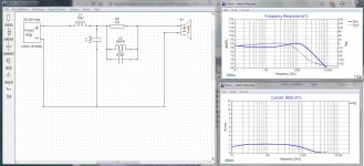
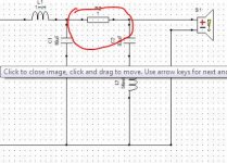
See the attached thumbnail... The OP was asking for a 5db 70hz notch in his crossover. The lash up shows a second order crossover with a 70hz series resonant shunt filter... notice the current going through it... yep, that's 16 amps at 100 watts. It's an amp killer.
Doing it with EQ or DSP has the opposite effect, you get a narrower band of affected frequencies and turning things down actually reduces the load on your amplifier.
Attachments

Last edited:
I guess you right, it's not worth it. There is an option that if I move the speaker to another position,it's better. Only reason I didn't do this obvious cure is because I have something else in that spot, maybe time to rearrange the room a bit.
That sounds like a much better idea. See my reply to AllenB...
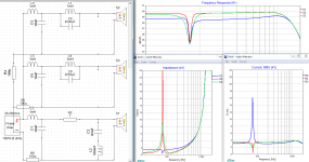
Here is a second lash up using a parallel resonant stop filter...
This one doesn't get crazy on current but it affects almost the entire range of the woofer as in bye-bye-bass.
This one doesn't get crazy on current but it affects almost the entire range of the woofer as in bye-bye-bass.
Attachments
Last edited:
Although I"m a big fan of passive crossovers, I don't see this as practical. 70Hz is low enough that it means huge values. Where are you going to find that 56mH inductor that Douglas has been kind enough to calculate?
This is about damping. Firstly, 6V6 hasn't shown the bandwidth of his peak.
If necessary, damping can be reduced by using a high Q inductor (low resistance). A filter could then use a much lower value of inductance.
If necessary, damping can be reduced by using a high Q inductor (low resistance). A filter could then use a much lower value of inductance.
This is about damping. Firstly, 6V6 hasn't shown the bandwidth of his peak.
If necessary, damping can be reduced by using a high Q inductor (low resistance). A filter could then use a much lower value of inductance.
I'm sorry... I seem to be having a bad day today. Perhaps I'm just not explaining myself very well...
Look at the first Sim I posted. Okay, do you see that big red spike in current at 70hz? That is going to still happen no matter the Q of your filter.
Now a little math tells us that a 100 watt amplifier, which is what that sim is tuned to, expects to produce about 28v across 8 ohms ... about 3.5 amps.
Now what do think happens if you ask it for 15 or 16 amps?
That shunt filter is going to look for all the world like a short circuit.
That is to say that a filter constructed like the one in the Sim is likely to damage the amplifier it's connected to, at the very least it's going to drive it into protection.
Or more succinctly ... it's an amp killer
Even at lower volumes it's going to suck the life right out of the speaker. It will sound weak and constrained as the amp struggles with an unexpected load.
What more is there to discuss???
Last edited:
And why on Earth would you use such a filter in such a way?Second, these filters are almost always a series resonant shunt filter 😱which will increase amplifier current significantly at the center band of the filter.
See the attached thumbnail... The OP was asking for a 5db 70hz notch in his crossover. The lash up shows a second order crossover with a 70hz series resonant shunt filter... notice the current going through it... yep, that's 16 amps at 100 watts. It's an amp killer.
Calling it a bad choice or bad engineering is *praising* it.
Of course a bad design will behave horribly.
What you need is a parallel resonant filter "tank" , in series with woofer, period.
Since only 5dB attenuation is needed, it will be shunted by an approximately 8 to 10 ohm resistor, whatever´s needed.
No big deal to drive by any reasonable amplifier.
And why on Earth would you use such a filter in such a way?
What you need is a parallel resonant filter "tank" , in series with woofer, period.
Since only 5dB attenuation is needed, it will be shunted by an approximately 8 to 10 ohm resistor, whatever´s needed.
No big deal to drive by any reasonable amplifier.
I'm guessing you didn't see the second sim I posted using a parallel resonant "stop" filter, and the effect the shunt resistor had across almost the entire first 500 or so hertz. Shunting it with a resistor only reduces it's Q and distributes its effects more widely.
As I told the OP... this is going to mess up his system more than any EQ or DSP ever could.
Calling it a bad choice or bad engineering is *praising* it.
Of course a bad design will behave horribly.
Yet I see them used all the time, and not just in DIY designs either.
I recently tore the crossovers out of my Cambridge Audio SX-60s and replaced them for this very reason.
Last edited:
Honestly, there's an easy fix to Douglas's series notch filter presenting an almost short circuit to the amplifer at around 70c/s, is to put a 2.7 ohm 10 watt ? resistor in series with the input to the LR2 filter, (that is, input.....2.7 ohms resistor........1 mH inductor). This will raise the impedance seen by the amplifier at 70c/s to 4.4 ohms. Nearly all amplifers these days would not flinch at that.
C.M
C.M
Last edited:
Yep that would raise the impedance alright... and drop the overall output from the woofer by about 6db.
Plus, there already is an input resistor in that filter...
Plus, there already is an input resistor in that filter...
Attachments
Last edited:
Higher Q filters can be sensitive to parasitics. I like to swamp a resonance with a sufficient resistor but here there's barely the luxury (as has already been shown).
Using Douglas' filter shape (blue), I wanted to set a baseline (red). This has no resistance in the loop between the capacitor and the inductor, so it is unrealistic. It shows the minimum inductance that will work in this configuration.
I put 0.1 ohms in the loop (green) and changed the values to get the peak back to 5dB. The Q has changed. The inductor resistance (and the capacitor's) will be critical in this configuration.
I also changed the current sense conditions so as to accomodate the different configurations fairly.
At this point this sim has too low impedance in general so isn't ready for use, just perusal.AllenB said:damping can be reduced by using a high Q inductor (low resistance). A filter could then use a much lower value of inductance.
Using Douglas' filter shape (blue), I wanted to set a baseline (red). This has no resistance in the loop between the capacitor and the inductor, so it is unrealistic. It shows the minimum inductance that will work in this configuration.
I put 0.1 ohms in the loop (green) and changed the values to get the peak back to 5dB. The Q has changed. The inductor resistance (and the capacitor's) will be critical in this configuration.
I also changed the current sense conditions so as to accomodate the different configurations fairly.
Attachments
Last edited:
A stop filter does solve the high current problem... but the OP was only looking for a 5db dip. That would mean putting a resistor across the tank circuit to limit it's effect, which would totally destroy the Q of the filter as my second sim (Post #7) shows. Download it and set the resitor R2 to Open and watch what the frequency response does...
There is quite literally no way of doing this without a severe downside... either he looses all output from about 40 to 100 hz, the bass is carved out by a low Q filter or the overall bass level is dropped by several DB... or, heaven forbid, he cooks the outputs on his amp.
No offense to the OP... but all this silliness has actually been over a quirk in room accoustics that I seriously doubt anyone would pick up on without REW and a microphone. Most rooms are +-10db or more, all by themselves. If you get speakers into a room with less variation than that, you are one seriously lucky stiff.
I have a node in my listening/living room at 74hz that displaces the sound out of the stereo image and makes it sound like it's coming from my balcony door 8 feet to the right of my setup. I could probably set up bass traps, juggle my furniture a bit, add sound absorbers and straighten that right out... but you know what... it's a living room not a recording studio... I can live with it.
Last edited:
I was showing 5dB? and there is no need for conductance across the loop when the resistance within it does the same thing and is the right amount.but the OP was only looking for a 5db dip. That would mean putting a resistor across the tank circuit to limit it's effect, which would totally destroy the Q of the filter
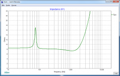
I made a mistake using Xsim as I'm not used to it (I used it so I could expand on your work). Here's the impedance.or, heaven forbid, he cooks the outputs on his amp.
Attachments
- Home
- Loudspeakers
- Multi-Way
- Equalizing one channel only using capacitor?