Finding the right amount and the right places is where it becomes not quite simple, and imo impossible by merely guessing or using a uniform approach and putting a given treatment in the same place all the time...
At this time it should be noted that EnABL1 put the rings in a generic place, EnABL2 has the cone telling us where to put the rings. The "measurement" used for ring placement requires the ear/brain as a detector (at least at this time).
dave
I suggested years ago Bud has applied principle of phononic crystal.
"phononic crystal" - Google Search
"phononic crystal" - Google Search
For EnABL 2.0 we do indeed find specific locations for ring placement across the radial distance of the cone surface. The placement positions are different for each specific cone, though a general set of common rules do seem to apply to specific types. As an example, the Fostex 127 drivers utilize a cone that is similar enough to the Fostex 126 driver that the patterns are applied in the same locations with the same audible results. A Mark Audio Alpair 7 driver is the same general size, made from aluminum rather than banana leaf paper, but also a curvilinear cone without whizzer cone. The patterns are slightly fewer in number and their locations, though grouped on the same radial "zone" of the cone, are in slightly different places.
dlr, your use of a curvilinear cone for your experiments just makes your work even more interesting. At some point it might be very intriguing to treat a driver with both activities. I can certainly provide our pattern locations for your cones should I happen to get hold of one for a day or two. They may, or may not lead you to a refinement in your work. It would be neat to end up with the benefits of both investigations. I don't think we would find them to be in conflict or overlapping each other in utility.
Bud
I suggested years ago Bud has applied principle of phononic crystal.
Frank,
I do remember that and did read up on them. I must point out that if I am indeed applying those structures it is as an "idiot savant" since I do not understand the implications of the diffraction structures as they apply to cones. In fact, I don't think I understand what I read, at all.
Bud
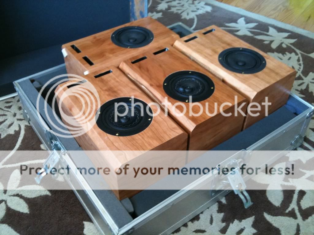
Dave (P10) lent me two matched pairs of EL70s. 1 pair stock. 1 pair enabled. I'll be posting some more details when I get around to it, about listening impressions. It should be noted at this time, that the only differences I could hear, were in the treble range, which is the only region showing a measurable change. I did prefer the enable treble range, however it looks like it measured worse. I measured AFTER I listened.
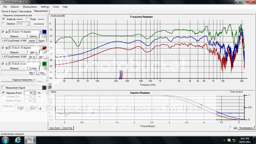
Stock (spliced at 350hz)
enabled (spliced at 350hz)
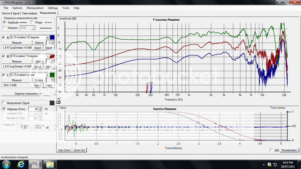
Other than a gate NO smoothing was used.
It doesn't appear to me that enable gives better off axis dispersion. This was also confirmed before measurements in my listening session where standing up out of my LP killed off the upper treble range.
EDIT - I'll explain this more in detail later, but the differences between these pairs was more than just enable. Dave gave the enabled pair his full treatment of cone treatment, and a smoothing ring around the magnet where it meets the basket. Dave could offer more insight as to what was done.
And does anyone know how to get CSD out of these impulse measurements?
Last edited:
Dlr,Do you believe that the human ear can reliably detect phase shift due to crossover group delay with music, not a test signal? If the answer to the first question above was yes, then the answer to this must be yes If the answers are yes, on what basis have you come to this conclusion?. Has any serious scholarly study ever shown this to be the case with music and not special test signals through headphones? Remember, we're speaking of typical drivers, not headphones nor earphones.
I'd like to see direct answers.
For that question, I'd say anyone of your skill level can, when using a PC-based system with FIR-filtering and a bit of effort, readily find this out themselves by own serious experimenting. In this case it is particularily easy to make no other changes than to overall phase response (or polarity, same cake) and to provide for bullet-proof ABX-testing, including controls. No need to wait for rigorous study. And even when it comes, eventually it will (probably not from the AES), you still will not know whether it is repeatable by or any relevant for you except by trying.
- Klaus
...the only differences I could hear, were in the treble range, which is the only region showing a measurable change. I did prefer the enable treble range, however it looks like it measured worse.
Ryan,
Once overlayed differences are not much... within the realm of unit-to-unit variation.
You heard no difference in the soundstage?
dave
Attachments

The stiffer the cone material is, the more difficult it is to find a solution. But it is still possible.And if this driver is crossed over at, say 2khz, all modifications with added weight become pretty much irrelevant. I recently found out that all my aluminum driver cone treatments were useless.
Twisterspeakers DIY loudspeaker projects: aluminum woofers' cone treatment experiment
dlr, have you tried to take measurements with wool felt placed in front of the driver (covering entire radiating area).
If it's not a metal driver, there should be nice acoustic roll off.
Did not realize this thread was still going so strong. Just started getting some notices in the last few days.
I've already done that, last year using the Ultimate Equalizer, just not ABX. Can't say that I'm interested in an ABX test since with sighted testing I did not hear a difference between minimum-phase and linear phase response.Dlr,
For that question, I'd say anyone of your skill level can, when using a PC-based system with FIR-filtering and a bit of effort, readily find this out themselves by own serious experimenting. In this case it is particularily easy to make no other changes than to overall phase response (or polarity, same cake) and to provide for bullet-proof ABX-testing, including controls. No need to wait for rigorous study. And even when it comes, eventually it will (probably not from the AES), you still will not know whether it is repeatable by or any relevant for you except by trying.
- Klaus
Dave
Where did you place the start of the window? I would expect to see the window on the rise side fairly close to the impulse.
Stock (spliced at 350hz)
[IMG]https://i874.photobucket.com/albums/ab306/tuxedocivic/eNable/EL70stock.png
enabled (spliced at 350hz)
Other than a gate NO smoothing was used.
This is not surprising.It doesn't appear to me that enable gives better off axis dispersion. This was also confirmed before measurements in my listening session where standing up out of my LP killed off the upper treble range.
Dave
I haven't read through all of this mammoth thread, (I gave up when it descended into a flame war) only skimmed through it briefly, but some aspects of "EnABL" seem to be similar to what I've been doing for years.Seems to me that Bud's approach is intended to effect the nodes and breakup modes on the surface of the cone - never mind the "boundary layer" claim - and may have some merit IF one could in essence "fractalize" or "randomize" these modes on the surface (spreading them?) just the right amount. Finding the right amount and the right places is where it becomes not quite simple, and imo impossible by merely guessing or using a uniform approach and putting a given treatment in the same place all the time...
I've discussed my approach in a few other threads but most recently and succinctly in this one, starting at post #43:
http://www.diyaudio.com/forums/multi-way/192215-phase-plug.html#post2640287
and provided some measurements and theorizing here in post #45: (and later)
http://www.diyaudio.com/forums/multi-way/192215-phase-plug.html#post2640803
I don't remember exactly when I first experimented with this method, but it must have been some time between 2001 and 2003, and until finding this EnABL thread here on diyaudio a couple of months ago I've never come across any literature or discussion on similar techniques, even though I've looked. At the time my measurement system was fairly limited so the quality of my old measurements is not great (no gating to remove room reflections) but still indicative of a real change.
All drivers that I tested on were 8" paper cone full range drivers, and I've successfully done a total of about 12 drivers.
I'd suggest reading from post #43 onwards in that thread for a full description, but a quick summary of my findings:
1) The effect of placing damping (in my case, a number of adhesive rectangular foam strips) further in than the very edge of the cone does have a different effect than just changing the damping of the surround, or adding damping at the surround/cone junction, as for example in one of dlr's posts in the other thread.
2) Staggering the damping at two alternating radial distances seems to be key to getting the flattest response. If all the strips are at the same distance from the centre the result is not as good. I believe (but can't prove) that this is because it is breaking up the cone into separate sectors or "pizza slices" which have non-identical standing wave patterns.
Normally a circular cone would have the same standing wave pattern at a given frequency at any angle from the centre to edge, thus the resonances of every angular rotation of the cone fall at the same spot frequencies. By staggering the position of the strips the resonances spread out and also partially cancel each other. (The foam strips also add some resistive losses, just like surround damping)
3) The number of strips around the perimeter at each radius seems important. I've found 4 and 8 work well. Some other numbers don't, including 2. Overall symmetry is important too.
4) Every individual driver is different, there is no one size fits all pattern, and it took me a lot of trial and error to optimize each individual driver. Even though all the drivers I did were very similar 8" drivers (Coral Flat 8 and similar) the final patterns were significantly different, although there were certain trends that followed which allowed me to more quickly home in on the optimal pattern once I had learnt those trends. (The pattern presented in the other thread is just the one I used on one particular driver pair, and even between the two drivers in that pair there are small differences in my pattern) Because every driver is different, just placing a "standard" template on a driver is just as likely to make the response worse as better.
5) One reason I think the strips work so well compared to say just making the cone more lossy, or doping the cone surface (again a theory I can't prove) is that the bending wave tries to bend the paper, and because the foam strip is relatively thick (3mm in my case) the bending of the paper that the foam is strongly stuck to attempts to stretch and squash the foam. So even though the foam doesn't terminate anywhere like a surround would, being stuck only to the cone, it's still able to absorb a lot of energy from the bending action of the cone.
6) Obviously some cone materials don't suit a modification like this. I doubt it would work well on a metal cone for example although I haven't tried it. I'm sure there are plenty of drivers where there would be minimal effect or where it would make things worse.
I think the cone operation on a driver working well past breakup at high frequencies (like a full ranger) is incredibly complex, probably more so than even some experts think. I don't think just making the cone or the surround homogeneously more lossy is the solution to getting a smooth but extended high end response, I really do think that the right pattern and application of damping can flatten out the response a lot more but without the loss of overall high frequency response that a lossy cone entails.I say this with the understanding that what a cone driver is actually doing is in reality a fine mess to start with. Smoothing out the mess may not be a bad idea at all... (assuming you see it as I describe).
I think how to do that is the real issue and where the best solution(s) may be found??
_-_-bear
Last edited:
That's perfect and OK, too. Plus it illustrates that the issue is subtle and not likely a deal killer.I've already done that, last year using the Ultimate Equalizer, just not ABX. Can't say that I'm interested in an ABX test since with sighted testing I did not hear a difference between minimum-phase and linear phase response.
Dave
You might try the other way round one time, using a bigger FR in OB and then bring in allpasses (analog will do). Admittedly it took me very transparent speakers myself to significantly notice the effect on ambience/soundstaging, while the change in timbre and tightness in the bass was easy to detect even with my old passive JBL 3way floorstanders as well as my Tannoy nearfields, but not with headphones which I just hate anyway (both maybe because I'm a bass player).
-----------:-----------
Interested in a simple test signal for timbre shift from phase shift, anyway? Just mix a sine with its octave at the the same level, but with a constant offset of 0.5Hz (eg 300Hz and 600.5Hz). Use a set of frequencies from 50Hz to 400Hz or so. While the spectrum is two plain needles standing there rock solid it does not sound like that. True 2nd harmonic does, but also changes timbre when the start phase of the 2nd is rotated some amount.
This 100% H2 (or H2+delta) signal is quite similar to eg some electric bass guitar signals and IHMO clearly illustrates the effect of phase (from allpasses as well as bass roll-offs) on timbre as one aspect of the phase/polarity issue. EDIT : checks for low distortion must be made, of course.
Assumed cause (by me, partially) for this effect and possibly for a lot of other LF anomalies of the ear is the sort of have-wave rectifying response of the neurons firing which seems to exist. There's a presentation by David Griesinger where this is noted (alas with no further references I could find there).
- Klaus (sorry @all for the OT)
Last edited:
Interested in a simple test signal for timbre shift from phase shift, anyway? Just mix a sine with its octave at the the same level, but with a constant offset of 0.5Hz (eg 300Hz and 600.5Hz). Use a set of frequencies from 50Hz to 400Hz or so. While the spectrum is two plain needles standing there rock solid it does not sound like that.
It sounds like that to me. What should that test show?
Just a thought.
I have been thinking about this question. What does EnABL actually produce in a driver? Could it be like the following?
Ever drive a car that has a solid rear axle? Not, an independent suspension? The solid axle with transmit bumps and thuds throughout the entire rear section of the car even if only the right tire was the one that hit the object. But, with an independent suspension? The bump would not transmitted through the entire back of the car and be felt much less.
Likewise.. Does not EnABL in essence break up the effect of a resonances of a driver, turning it into an independent suspension of sorts? In doing so, it minimizes (not eliminate totally)certain resonance problems that would otherwise be expressed over the entire driver at the point it would take place?
Ryan,
Once overlayed differences are not much... within the realm of unit-to-unit variation.
You heard no difference in the soundstage?
dave
Soundstage changes weren't detectable to me between units. You're right, the FR differences are easily within unit variations, and mic placement. As I had to move things around to change between the two.
Comparing the impulse response of stock vs EnABL'd is interesting.
Any ideas on why is there such a difference?
Cheers,
Alex
They were measured one after the other. The scales are different. But, still some differences. I'll zoom in better and post some larger screen shots of the impulse when I have some time. Other wise, I can't really explain it. The baseline was a combined nearfield and 1m farfield spliced at 350hz averaged 50hz either side of 350hz. So the impulse looks a little goofy for those. I might have the unspliced impulses saved. I'll take a look when I get the larger impulses.
Where did you place the start of the window? I would expect to see the window on the rise side fairly close to the impulse.
This is not surprising.
Dave
Starts around 3ms. Why near the impulse?
For those interested (I should have taken a picture), the speaker was elevated to 1.2m above the floor in a room with 2.4m ceilings. The speaker was a minimum 1.7m away from the nearest wall. The mic wall measured 1.0m away from the baffle. The mic was measured 1cm from the dust cap in the nearfield test. The floor was dampened with some blankets, although that is more for peace of mind rather than it actually doing anything 😉
HOLMAcoustics resets the start time marker to the beginning of the sampling IIRC. At least it always did with the settings I was using. If you don't set the start time marker to a point close to the actual impulse, then the data includes pre-impulse data that is room background noise which does not represent the response of the driver alone.Starts around 3ms. Why near the impulse?
For those interested (I should have taken a picture), the speaker was elevated to 1.2m above the floor in a room with 2.4m ceilings. The speaker was a minimum 1.7m away from the nearest wall. The mic wall measured 1.0m away from the baffle. The mic was measured 1cm from the dust cap in the nearfield test. The floor was dampened with some blankets, although that is more for peace of mind rather than it actually doing anything 😉
Dave
How high was the low pass cutoff frequency for tweeter?I've already done that, last year using the Ultimate Equalizer, just not ABX. Can't say that I'm interested in an ABX test since with sighted testing I did not hear a difference between minimum-phase and linear phase response.
Dave
If we look back to the beginning of all this, there was a water tank example. Basically when soft diaphragm material is used, you get similar effects. But since pattern effectiveness depends on frequency/wave length, if the right pattern is used, the more effective it is. Of course there is also the mass distribution effect. Properly distributed mass also helps.Just a thought.
I have been thinking about this question. What does EnABL actually produce in a driver? Could it be like the following?
Ever drive a car that has a solid rear axle? Not, an independent suspension? The solid axle with transmit bumps and thuds throughout the entire rear section of the car even if only the right tire was the one that hit the object. But, with an independent suspension? The bump would not transmitted through the entire back of the car and be felt much less.
Likewise.. Does not EnABL in essence break up the effect of a resonances of a driver, turning it into an independent suspension of sorts? In doing so, it minimizes (not eliminate totally)certain resonance problems that would otherwise be expressed over the entire driver at the point it would take place?
As shown in my tests of a few years ago, the rising pattern also effects how acoustic waves travel along the cone surface which is also cone shape dependent. To obtain more optimal performance, all these need to be considered, and possibly each focusing on a limited frequency range.
- Home
- Loudspeakers
- Multi-Way
- EnABL - Technical discussion