Can you share files(schematic&pcb)from your smps?
Hi thimios!
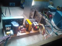
Find the sprint file in the attachment, my build is part hand drawn because I modified it to accomodate IGBTs, it is Detex Audio circuit self oscillating smps topology. It is very popular in this part of the world, you can join the Indonesian group S.O.S (self oscillating smps) in Facebook and find out how are they doing it. SMPS is very challenging to DIY you should try it, you have the equipment..😉
Regards,
Albert
(Sorry bimo, O.T.)
Attachments
Oh yes..this reminds me of my Tekukur build, I don't have Sanken's so I used 2sc5200/sa1943 with some values adjustment, it sounds powerful in my diy smps....😉
CFP or Sziklai configuration of output stage make bass more punch. Maybe because H3 distortion dominant at low frequency?
Yes, SMPS also make bass seem more powerful. But all DIY SMPS that I tried make degradation of mid and high frequency quality. Maybe EMI or high frequency ripple on SMPS?
Hi bimo!
Could be an smps topology issue? Self oscillating seems to be popular to audio enthusiasts in this region..the Indonesian group that I mentioned above are doing it differently, the secondary caps are made of multiple small value caps and they are using toroids rather than EE ferrites most probably to boost regulation efficiency and they are pushing it to work above 100khz fsw (Detex default is about 100khz).
Regards,
Albert
BTW..from what I gather magnetizing field of toroids is confined in the center and the fringing flux that occurs is suppressed. (fringing flux is bad to audio am I right?) I intentionally placed my smps build near the amp with everything exposed to see how it affects the operation. So far I haven't noticed any audio disturbances visible to the eye and audible to the ears..but I'm no expert here...🙂
Last edited:
Hi thimios!
Find the sprint file in the attachment, my build is part hand drawn because I modified it to accomodate IGBTs, it is Detex Audio circuit self oscillating smps topology. It is very popular in this part of the world, you can join the Indonesian group S.O.S (self oscillating smps) in Facebook and find out how are they doing it. SMPS is very challenging to DIY you should try it, you have the equipment..😉
Regards,
Albert
(Sorry bimo, O.T.)
Thanks Albert!I haven't tried any diy SMPS due to transformer difficulties.CFP or Sziklai configuration of output stage make bass more punch. Maybe because H3 distortion dominant at low frequency?
Yes, SMPS also make bass seem more powerful. But all DIY SMPS that I tried make degradation of mid and high frequency quality. Maybe EMI or high frequency ripple on SMPS?
Bimo,did you tried commercial SMPS and what is your opinion?
Hi bimo!
Could be an smps topology issue?
I do not know the topology. I just tried several DIY SMPS that made by some friends. The degradation is small but experienced listener can easily hear it.
I did not measure it yet, but i think the distortion is rise.
Edit:
I plan use SMPS for audio pro (live music) application. But definitely not in hi-fi. I plan add LC filter on SMPS output to see if it is good enough for hi-fi or not.
Last edited:
Thanks Albert!I haven't tried any diy SMPS due to transformer difficulties.
Bimo,did you tried commercial SMPS and what is your opinion?
There are tutorials on Yuotube on how to construct the traffos, diysmps.com had plenty of reading materials on how to do it homemade. I think you are capable plus you have measuring instruments. 🙂
This is my modification.
Thank you Bimo ! Sorry I did not see this thread earlier !
Last edited:
Dear Bimo,
As this emprit amp is working on +/- 25 Volts only, It is a good candidate for single supply operation. We can for get about loudspeaker protection. Can you kindly provide modification of this amp to Single supply and simulation files?
--gannaji
As this emprit amp is working on +/- 25 Volts only, It is a good candidate for single supply operation. We can for get about loudspeaker protection. Can you kindly provide modification of this amp to Single supply and simulation files?
--gannaji
Emprit Retromod
Dear bimo,
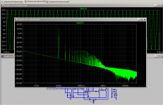
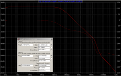
As an exercise, I started with your .asc file from post #20 and modified it to Retro mod. The results are as below. Kindly comment on the results.
--gannaji
Dear bimo,
As an exercise, I started with your .asc file from post #20 and modified it to Retro mod. The results are as below. Kindly comment on the results.
--gannaji
Attachments
Dear bimo,
As an exercise, I started with your .asc file from post #20 and modified it to Retro mod. The results are as below. Kindly comment on the results.
--gannaji
Good stability.
You should build it and measure it.
If the measurements far away from simulation, maybe your pcb layout is bad.
The LTP tail voltage and current regulator with LEDs is a bit cumbersome in the retro version. Can it be made simpler ?
- Status
- Not open for further replies.
- Home
- Amplifiers
- Solid State
- Emprit Amplifier