Question:
Do we really need emitter resistors (ballast resistor,
or whatever the correct name is in case of FETs)
in single pair HexFet OPS?
I've seen numerous claims in literature that they are
not really needed, but still most of schematics do include
them, even with one pair of output devices.
Do we really need emitter resistors (ballast resistor,
or whatever the correct name is in case of FETs)
in single pair HexFet OPS?
I've seen numerous claims in literature that they are
not really needed, but still most of schematics do include
them, even with one pair of output devices.
They aren't needed in lateral mosfet amps as the transistors have already adjust their resistance for temperature.
With none laterals you don't get that so a resistor in source line gives a bit of degeneration and extra stability.
With none laterals you don't get that so a resistor in source line gives a bit of degeneration and extra stability.
They aren't needed in lateral mosfet amps as the transistors have already adjust their resistance for temperature.
With none laterals you don't get that so a resistor in source line gives a bit of degeneration and extra stability.
How much stability we gonna get from 0.22 Ohm?
How much stability we gonna get from 0.22 Ohm?
Depends on the amount of bias current. The more bias current, the more quiescent degenerative feedback. At any rate, some is better than none, as far as stability is concerned. It's like getting a tiny raise in your paycheck. A little is better than none at all.
Do you mean single, like a total of two transistors for one amplifier, or a single pair for the negative side, and another one for the +side?Question:
Do we really need emitter resistors (ballast resistor,
or whatever the correct name is in case of FETs)
in single pair HexFet OPS?
If it is the first possibility, it depends on the topology: if it's in a C variant, no, for many other types, yes.
If you parallel devices (4 transistor/amplifier), then with vertical types they are needed, just like for BJT: they have a negative tempco too.
They are not as critical as for BJT's, because of inherent resistances, but they are necessary.
Perhaps even more important is the matching: BJT's have an excellent consistency, but VDMOS transistors tend to have a much wider spread, and without matching, one of the devices will probably end taking all of the current
Do you mean single, like a total of two transistors for one amplifier, or a single pair for the negative side, and another one for the +side?
I mean two output transistors in total.
One 'upper' transistor, and one 'lower' transistor.
They definitely help to linearize and stabilize output MosFets.
You seem to be under the wrong impression that "0.22 ohms is "almost" 0 ohms so why bother?"
Wrong assumption.
Remember *amperes* are passing through them, and voltage drop across them is significant.
In general, it´s good safe Engineering using them.
You seem to be under the wrong impression that "0.22 ohms is "almost" 0 ohms so why bother?"
Wrong assumption.
Remember *amperes* are passing through them, and voltage drop across them is significant.
In general, it´s good safe Engineering using them.
They definitely help to linearize and stabilize output MosFets.
Quote from Randy Slone:
"While it is true that degenerative feedback improves linearity, the low-resistant values of RE resistors necessary for reasonable OPS efficiency reduces their linearizing contribution to negligible levels"
Now, what "stabilize" actually means in this case?
I guess not thermal stability, because we are not sharing current (no parallel devices).
So what is it? Prevents fets from oscillating?
Just trying to understand what exactly these resistors do in this case.
In this case, it depends on the topology: most of the classical schemes use some kind of temperature-compensated gate-spreader, and the source resistors are part of that scheme: they give some slack.I mean two output transistors in total.
One 'upper' transistor, and one 'lower' transistor.
Without them, tiny variations/differences in temperature would result in large currents.
Non-classical schemes like the C sense and servo the currents in other ways, but it is impossible to give a general answer.
In this case, it depends on the topology: most of the classical schemes use some kind of temperature-compensated gate-spreader, and the source resistors are part of that scheme: they give some slack.
Without them, tiny variations/differences in temperature would result in large currents.
Non-classical schemes like the C sense and servo the currents in other ways, but it is impossible to give a general answer.
I see. So after all, it sounds like it IS about thermal stability.
So for classical schemes, with thermal BIAS tracking, even though we are not paralleling devices, emitter resistors are helping to equalize
the current between upper/lower devices??
Not sure how this works...
We do need to adjust bias via thermal tracking..
No, they simply ensure the stability of the quiescent current and prevent thermal runaway, just like in a BJT amplifierSo for classical schemes, with thermal BIAS tracking, even though we are not paralleling devices, emitter resistors are helping to equalize
the current between upper/lower devices??
Local Bias Thermal Stability
Hi minek123,
Bo Cordell covers this from p405 (2nd Ed). Thermal runaway without source degeneration resistors can occur if the thermal loop gain is greater than unity. The thermal loop gain is the product of 4 terms:
The temp-co of the MOSFET eg -6mV/C for an IRFP240
The Gm of the MOSFET bias current (eg at the turn on)
The thermal resistance from junction up to the bias sense point
The rail voltage (for a split rail amp).
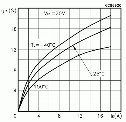
Looking at the IRF640 Gm vs Id plot (no data for the IRFP240 but is usually the same die) we see the Gm is about 3A/V at 1 amp and we can interpolate for lower bias current of say 0.3A to get 1A/V.
The thermal resistance of an IRFP240 from junction to case is around 1.1C/W and then add around 0.5C/W for the thermal washer giving around 1.6C/W to the heatsink. To the bias sensor assume a bit extra say total now 2C/W. For an IRF640 TO-220 it is closer to 3C/W.
Now multiply all these and we get 6mV/C * 1A/V * Vrail * 2C/W <=1
Solve for Vrail <= 1/12m or
Vrail <83 Volts for the IRFP240 with no source resistors.
For the IRF640 <= 56 Volts with no source resistors.
If you use less bias the maximum thermally stable rail voltage increases. If you use more bias the rail voltage decreases!
If you have the SPICE model Kp then you can use that since Gm vs Id plots are not always available. The Gm vs Id for a MOSFET at lower currents is approximately
. Gm=Sqrt(2*Kp) * Sqrt(Id)
EG the IRFP240 has a KP of around 6-9A/V^2 giving a Gm of around 1A/V at 0.3A (like as from the Gm plot).
Now for your amp with a single pair of vertical MOSFET's like the IRFP240/9240.
Since a single pair cannot do much more than 50W for SOA reasons you should not use rail voltages over 35V in which case no source resistors will not lead to thermal runaway if your bias sensor is working properly and is reliable (bolted to the heatsink for peace of mind).
You can use the IRF640 TO-220 without source resistors as well.
For other MOSFETs you can do the sums and find out whether it is safe to use no source resistors in your Class-AB amp. For parallel MOSFET's the calculation applies to one of the group and as Elvee pointed out above you must match the threshold voltages closely so they share currents reasonably well without source resistors. EG 30% match in Id at 0.3A idle is a 100mA and the Gm is 1A/V there so +/-100mV matching is need for the gate voltages.
BTW the more recent trench FETs with their much higher Gm and Kp values are not generally thermally stable with no source resistors in linear mode like power amplifiers and need source degeneration resistors to get the thermal loop gain below unit for stability.
Lastly, I have found not using source resistors in MOSFET Class-AB stages does make a big difference to the distortion at the lower power levels like up to 1W where it matters the most. I note Nelson Pass has recently found not using source resistors in Class-A has real benefits, including better sound quality, particularly for low feedback vertical power MOSFET amps Nelson Pass BAF 2019.
Cheers,
Hi minek123,
Bo Cordell covers this from p405 (2nd Ed). Thermal runaway without source degeneration resistors can occur if the thermal loop gain is greater than unity. The thermal loop gain is the product of 4 terms:
The temp-co of the MOSFET eg -6mV/C for an IRFP240
The Gm of the MOSFET bias current (eg at the turn on)
The thermal resistance from junction up to the bias sense point
The rail voltage (for a split rail amp).
Looking at the IRF640 Gm vs Id plot (no data for the IRFP240 but is usually the same die) we see the Gm is about 3A/V at 1 amp and we can interpolate for lower bias current of say 0.3A to get 1A/V.
The thermal resistance of an IRFP240 from junction to case is around 1.1C/W and then add around 0.5C/W for the thermal washer giving around 1.6C/W to the heatsink. To the bias sensor assume a bit extra say total now 2C/W. For an IRF640 TO-220 it is closer to 3C/W.
Now multiply all these and we get 6mV/C * 1A/V * Vrail * 2C/W <=1
Solve for Vrail <= 1/12m or
Vrail <83 Volts for the IRFP240 with no source resistors.
For the IRF640 <= 56 Volts with no source resistors.
If you use less bias the maximum thermally stable rail voltage increases. If you use more bias the rail voltage decreases!
If you have the SPICE model Kp then you can use that since Gm vs Id plots are not always available. The Gm vs Id for a MOSFET at lower currents is approximately
. Gm=Sqrt(2*Kp) * Sqrt(Id)
EG the IRFP240 has a KP of around 6-9A/V^2 giving a Gm of around 1A/V at 0.3A (like as from the Gm plot).
Now for your amp with a single pair of vertical MOSFET's like the IRFP240/9240.
Since a single pair cannot do much more than 50W for SOA reasons you should not use rail voltages over 35V in which case no source resistors will not lead to thermal runaway if your bias sensor is working properly and is reliable (bolted to the heatsink for peace of mind).
You can use the IRF640 TO-220 without source resistors as well.
For other MOSFETs you can do the sums and find out whether it is safe to use no source resistors in your Class-AB amp. For parallel MOSFET's the calculation applies to one of the group and as Elvee pointed out above you must match the threshold voltages closely so they share currents reasonably well without source resistors. EG 30% match in Id at 0.3A idle is a 100mA and the Gm is 1A/V there so +/-100mV matching is need for the gate voltages.
BTW the more recent trench FETs with their much higher Gm and Kp values are not generally thermally stable with no source resistors in linear mode like power amplifiers and need source degeneration resistors to get the thermal loop gain below unit for stability.
Lastly, I have found not using source resistors in MOSFET Class-AB stages does make a big difference to the distortion at the lower power levels like up to 1W where it matters the most. I note Nelson Pass has recently found not using source resistors in Class-A has real benefits, including better sound quality, particularly for low feedback vertical power MOSFET amps Nelson Pass BAF 2019.
Cheers,
Attachments

Last edited:
N and P vertical type devices are not equal, particularly at low current. Not true complements. Ballast resistors help alleviate the %difference, somewhat🙄 along with aiding thermal stability. Generally mosfets are more thermally stable due to much lower Gm at low bias current than BJT. Bias is usually set at least 300mA to keep Gm fairly🙄 linear through current crossover. (An exception might be if local EC is employed.) Devices are usually chosen based on similar Gm.
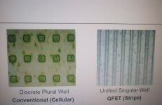
Trench and Nex-fet type are not well suited for linear operation. The die tends more to hot-spot. Choose one where heat is spread more evenly through the die. Like Hex-type (plural well) or stripe-type (singular well)
Trench and Nex-fet type are not well suited for linear operation. The die tends more to hot-spot. Choose one where heat is spread more evenly through the die. Like Hex-type (plural well) or stripe-type (singular well)
Attachments
N and P vertical type devices are not equal, particularly at low current. Not true complements. Ballast resistors help alleviate the %difference, somewhat🙄 along with aiding thermal stability. Generally mosfets are more thermally stable due to much lower Gm at low bias current than BJT. Bias is usually set at least 300mA to keep Gm fairly🙄 linear through current crossover. (An exception might be if local EC is employed.) Devices are usually chosen based on similar Gm.
Trench and Nex-fet type are not well suited for linear operation. The die tends more to hot-spot. Choose one where heat is spread more evenly through the die. Like Hex-type (plural well) or stripe-type (singular well)
The more I read about vertical fets, the less suitable they seem for audio applications.
Surprisingly, there is so many vertical fets amps designs here at DIY...
They are cheap and plentiful unlike latFETs, and older types were quite robust compared to BJT's.Surprisingly, there is so many vertical fets amps designs here at DIY...
Note that the static thermal stability condition represents the ultimate theoretical limit, and shouldn't be approached too much in practice because thermal problems are always complicated by various factors, and even if the static stability is ensured, the dynamic one is not, because of transmission delays and thermal time constants.
If a transient thermal event caused by a combination of difficult load and peculiar signal conditions occurs, it could well drive the OP into an unrecoverable high level thermal runaway, where the sensor always lags wrt to the actual source temperature.
Hefty safety margins are therefore highly advisable.
It's all in the application. Vertical mosfets are not BJTs. They are thier own thing, and you have to design the circuit specifically for those devices. Designs vary in complexity. Every devicetype has pros and cons. If you design a circuit to minimize or nullify the non linear issues with Gm and capacitances, and maximize the rate of heat dissipation from the die, vertical FETs really can make absolutely incredible output devices.😉
Many designs just modify BJT circuits and call it good enough.🙄. And then vertical FETs get a bad rep.

Many designs just modify BJT circuits and call it good enough.🙄. And then vertical FETs get a bad rep.
Some examples of vertical MOSFETs making great amps:It's all in the application. ... vertical FETs really can make absolutely incredible output devices.😉
Many designs just modify BJT circuits and call it good enough.🙄. And then vertical FETs get a bad rep.
1. 'A Zero Feedback Class A (AB) Power Amplifier' Zeus 75 - Zero Feedback Transformer Audio Power AmplifierSusan Parker "Zeus" 75W uses vertical MOSFETs with no source resistors. It is called zero feedback which means zero global feedback. It uses the MOSFETs as followers so uses local feedback. Around 0.1% THD at 1W.
2. Thorens TEM3200 'Blohbaum system' (or Blohebaum) is Circlotron like 6moons audioreviews: Thorens TEM 3200 - Sidebar III. Uses two huge SOT-227 vertical MOSFETs apparently with no source resistors.Wingspread plot below better than BJT output stages. Since two N-channel power MOSFETs are used there is not a match problem (as with standard complementary devices) and no need to match parallel devices without source resistors. A tube driver is used (presumably to give it a tube like sound) but solid-state drivers can be used (see examples on this forum). I posted one here India amp Rush Circlotron.
3. TDA7293 100W IC audio power amp uses all N-channel vertical MOSFETs aparently with no source resistors. IIRC it has the bias sensor intertwined with the power MOSFETs for fast bias correction for virtually no "memory distortion"😎
Attachments
Last edited:
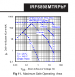
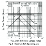
Since the mid-1990's, the lowest on-resistance vertical power MOSFETs usually suffer from Spirito instability, which is basically a kind of thermal second breakdown. Those are totally unusable for class-A, -B or -AB amplifiers, with or without source resistors, bias loops or whatever. They break down even when the total drain current is kept under control, because at highish drain-source voltages, the hottest spots of the MOSFET die start drawing more current, get even hotter and so on.
High-voltage power MOSFETs with a somewhat higher on resistance are usually still usable in class-A, -B or -AB amplifiers, especially at voltages far below the rated maximum VDS.
See the attachments for typical MOSFET SOAR curves. The first two are for MOSFETs with severe Spirito instability, the third one is for the IRFP240, which apparently has no Spirito instability. Mind you, in datasheets from the 1990's, the SOAR curves are not always reliable because the manufacturers were not aware of the issue yet.
Attachments

Last edited:
The more I read about vertical fets, the less suitable they seem for audio applications.
Surprisingly, there is so many vertical fets amps designs here at DIY...
I've built an amplifier with BUZ10 vertical power MOSFETs in 1994 and still use it every day. It works fine, but its topology is very different from most amplifiers. I chose BUZ10 MOSFETs because they were cheap and easy to drive: they have an enormous current gain at low frequencies and at high frequencies, their current gain is still much greater than that of cheap bipolar power transistors.
- Home
- Amplifiers
- Solid State
- Emitter resistor in HexFet OPS