Supercap bypass for DoubleCross emitter resistors
But still the improvement backs up my claims that with virtually no emitter resistors you get significantly lower crossover distortion with vertical MOSFETs. With supercap bypass the two sources effectively get shorted together by the capacitor above a few Hertz; the 10F supercap I specified has an ESR of 20m ohms between the sources for AC and the MOSFETs have another 20m to 40m ohms in their wire-bonds and metalization so you can't completely eliminate the degeneration and get distortion much lower in a vertical MOSFET stage.
------
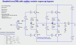
For the BJT output stage we can use two parallel stages and displace their center point either side of zero to get Bob Cordell's DoubleCross(TM) using supercap bypassing on each stage. The circuit is below:

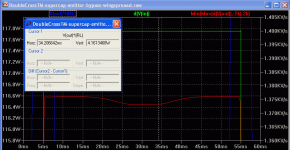
Biased for a total idle current of 330mA (same as for the vdmos OPS in post above) with a displacement voltage of +/-105mV below shows the near zero distortion region extends to 4W peak (2 watts average).

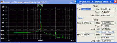
and the FFT below at 1 Watt average and THD is 0.0008% at 1W.

Looks promising for a no global feedback power amp.
The advantage of using supercaps to bypass the emitter resistors for AC in this circuit is the dynamic current sharing between parallel pairs is not impaired yet distortion is reduced.
As a reality check I still need to compare this output stage without the supercaps to check how much reduction in distortion is gained (if any). An electrothermal simulation might be able to answer this concern.
Also still unclear is whether a large 10F capacitor has any electrothermal side-effects with BJT's in the 1Hz-10Hz region. Vertical MOSFETs are probably safe (due to their lower Gm's). So it's still early days with BJT's for dynamic thermal stability with these large supercaps.
The THD improvement is actually slightly less than 10 times because I compared an optimized bias supercap stage with an un-optimised bias standard stage. This was because of the simple way I stepped the circuit between two cases with one run.So supercap helps reducing distortion with both HexFets and BJTs.
But still the improvement backs up my claims that with virtually no emitter resistors you get significantly lower crossover distortion with vertical MOSFETs. With supercap bypass the two sources effectively get shorted together by the capacitor above a few Hertz; the 10F supercap I specified has an ESR of 20m ohms between the sources for AC and the MOSFETs have another 20m to 40m ohms in their wire-bonds and metalization so you can't completely eliminate the degeneration and get distortion much lower in a vertical MOSFET stage.
------
For the BJT output stage we can use two parallel stages and displace their center point either side of zero to get Bob Cordell's DoubleCross(TM) using supercap bypassing on each stage. The circuit is below:
Biased for a total idle current of 330mA (same as for the vdmos OPS in post above) with a displacement voltage of +/-105mV below shows the near zero distortion region extends to 4W peak (2 watts average).
and the FFT below at 1 Watt average and THD is 0.0008% at 1W.
Looks promising for a no global feedback power amp.
The advantage of using supercaps to bypass the emitter resistors for AC in this circuit is the dynamic current sharing between parallel pairs is not impaired yet distortion is reduced.
As a reality check I still need to compare this output stage without the supercaps to check how much reduction in distortion is gained (if any). An electrothermal simulation might be able to answer this concern.
Also still unclear is whether a large 10F capacitor has any electrothermal side-effects with BJT's in the 1Hz-10Hz region. Vertical MOSFETs are probably safe (due to their lower Gm's). So it's still early days with BJT's for dynamic thermal stability with these large supercaps.
Attachments
I thought supercapacitors don't work above 1 Hz (PDF) Capacitance Characterization Methods and Ageing Behaviour of Supercapacitors
In the case of a dead short I can see the cap charging up and putting a strong reverse Vbe on one of the transistors.
Does the cap pump up in voltage at high powers? I would be worried that it would pump up, turn the transistors off and then that would cause an oscillation that keeps the cap overcharged. Though that may only occur with very low impedance loads. Try hanging a large capacitor off the output to induce oscillation?
It seems to me that the transistors can charge the cap faster than the emitter resistors can discharge it in the worst case. But maybe it is a non-issue.
Hi Dimitri,I thought supercapacitors don't work above 1 Hz (PDF) Capacitance Characterization Methods and Ageing Behaviour of Supercapacitors
Thanks so much for the info. It's not good news😱.
Obviously they are not usable for efficient energy storage close to their time constant and many are around 1 second (T = ESR * C) since half the energy gets lost in the ESR.
But the C number changes hugely with frequency! The paper you cited gives some plots of C at 1Hz 10Hz. EG Fig 7 at 10Hz shows 5% of rated C for a 350F cap. Fig 8 shows 12% of rated C at 10Hz for a 10F cap. I can't see any data for above 10Hz so I can't find if C continues to fall above 10Hz, or if it levels off.
I guess I will need to measure one.
Also anticipating a resonance frequency, a guess in the 10Hz-100Hz range, requires a parallel standard electrolytic to cover the audio range. The largest modest cost 6.3V electrolytic is 33mF (Nichon UVY or UVZ series). The crossover f-3dB at say 40mR is about 100Hz, so if the 10F resonance is also 100Hz then one 33mF standard cap would do the trick with a 10F cap to cover the audio range for this application. And for this application the operating voltage is only around 100mV (Ibias*0.22R*2).
Are there any SPICE models available for supercaps out there for 1Hz and above?
Hi keantoken,In the case of a dead short I can see the cap charging up and putting a strong reverse Vbe on one of the transistors...
With a standard DC coupled amps a prolonged high current output will be a fault condition and must be detected by speaker protection unit and the amp turned off.
If this supercap scheme turns out to be viable then the power amp needs a suitable input capacitor to roll-off the amp in the 1Hz to 10Hz range so the supercap doesn't get any unwanted DC on it.
BTW my simulation file includes a 2.5 cycle burst where you can see any change in capacitor voltage once the burst stops. Set the .Trans time for 3 cycles.
It's all good - supercaps seem to work OK above 1Hz-1kHz
Nice work! Thanks so much . It gives what we need and confirms supercaps can be used in this application!
Fig 8 shows a resonant frequency in the 300-600Hz range. From 20Hz to 3kHz the terminal impedance bottoms out at constant value (~ESR) so useable for audio with a shunt capacitor taking over from 1kHz and up.
Nice if the supercaps I am looking (Mouser or Farnell) behave much like the CAP-XX one in this datasheet.
Or one Cap-XX GS103 "cell" (0.5F 2.75V 20mR) would do the trick in the output stages I simulated above with one 5mF-30mF/6.3V electrolytic in parallel.
BTW Alex, there seems to be a typo in Fig 8 and Fig 9 where the X-axis is labelled as "Time(s)" and yet the label say "vs. frequency. Also the caption says "Frequency response". The plots make sense if the X-axis is read as Hz. Are you in contact with Cap-XX to let them know about this typo? Else I can email Pierre Mars (Engineering & Quality) or anyone else you can recommend to let them know about it.
Cheers,
Ian Hegglun
Hi alexberg,
Nice work! Thanks so much
. It gives what we need and confirms supercaps can be used in this application!Fig 8 shows a resonant frequency in the 300-600Hz range. From 20Hz to 3kHz the terminal impedance bottoms out at constant value (~ESR) so useable for audio with a shunt capacitor taking over from 1kHz and up.
Nice if the supercaps I am looking (Mouser or Farnell) behave much like the CAP-XX one in this datasheet.
Or one Cap-XX GS103 "cell" (0.5F 2.75V 20mR) would do the trick in the output stages I simulated above with one 5mF-30mF/6.3V electrolytic in parallel.
BTW Alex, there seems to be a typo in Fig 8 and Fig 9 where the X-axis is labelled as "Time(s)" and yet the label say "vs. frequency. Also the caption says "Frequency response". The plots make sense if the X-axis is read as Hz. Are you in contact with Cap-XX to let them know about this typo? Else I can email Pierre Mars (Engineering & Quality) or anyone else you can recommend to let them know about it.
Cheers,
Ian Hegglun
I do not see how capacitors can work with a class B OP: due to the rectification effect of the class B, the capacitors will progressively charge up during prolonged high output periods, and shift the bias of the OP towards cutoff.
During the loud passages this may not be noticeable, but if a quiet period follows, the program will suffer heavy Xover distortion until the capacitors have returned to their idle conditions.
With a class A OP, the average current remains the same for all output levels and there will be no such problem
That will happen to some extent, but maybe not too badly when, like Ian, you connect a single capacitor between the emitters or sources rather than one across each emitter or source resistor.
Hi Elvee,I do not see how capacitors can work with a class B OP: due to the rectification effect of the class B, the capacitors will progressively charge up during prolonged high output periods, and shift the bias of the OP towards cutoff...
Edit: Marcel. Thanks. Your post was sent when I was composing so I was unaware of it
.
Perhaps this is also the query by Keantoken Post 47 (and others). If a capacitor is placed across each source resistor then, sure, you get rectified DC charging each capacitor with signals.
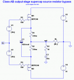
So I have been negligent to provide the circuit image in my post (I'm getting lazy). The VDMOS circuit is below.
With one capacitor across both resistors the DC components cancel out over whole cycles. My sim circuit available in Post 41 shows this with a burst of 2 cycles then nothing changed on the DC of the capacitor or bias currents.
For DC you have degeneration (as usual) for improved thermal stability. But for AC you have the two sources connected by a very low impedance (~ESR~20mR) which means closer to squarelaws which means closer to zero distortion.
Also for AC there is Rs/2 feeding to the load so the total gm is slightly higher giving even lower distortion from a follower..
And, when paralleling output pairs you have better AC current sharing due to this series Rs/2 for each pair.
This idea was not my own, it was suggested by Mark Aitchison who I did my engineering course with in NZ. He suggested it when he was proof reading my squarelaw amplifier article for Linear Audio Volume 1 around 2010.
Unfortunately supercapacitors were not suitable then, but now a low ESR capacitor of say 20 milliohms is only 10mm dia by 30mm for a few dollars ($5 1off in Aus). And the extra bypass electrolytic (5mF) is about the same size is only about one dollar.
Attachments
Last edited:
Indeed, it won't be as bad because the charging path will see one of the emitter or source resistors in series, but the discharging path will have both and the asymmetry will generate a charge accumulation.That will happen to some extent, but maybe not too badly when, like Ian, you connect a single capacitor between the emitters or sources rather than one across each emitter or source resistor.
How bad will it be in reality? I am not going to venture an opinion: after all, the Visch scheme has been (and probably still is) highly regarded.
This is a sim for a period of 10s, at near max power:
The green trace is the voltage across the cap: the bias shift is just under 400mV.
This is a zoom on the Xover region after the 10s period:
Iq clearly falls to zero. After a very loud passage, it might not be noticeable if the recovery time is sufficiently short, but I wouldn't bet on it
Attachments

Indeed, it won't be as bad because the charging path will see one of the emitter or source resistors in series, but the discharging path will have both and the asymmetry will generate a charge accumulation
Edit: a more correct and general analysis is that the average DC voltage across R1 or R2 is signal-dependent, and given their sign, they will add into C1.
Indeed, ... the asymmetry will generate a charge accumulation. ... Iq clearly falls to zero.
Hi Elvee,
Thanks for spotting that. It is a serious effect and needs a fix.
One way to keep the bias point about the same independent of signal level and duration is to bootstrap the bias voltages. See below (for proof of concept). You can run the attached circuit to probe the crossover points and try different signal levels to check how well it works.
V4 removes the idle voltage across R1+R2. For the bias used 338mA this is about 147mV. R5 and C3 removes most of the ripple from C1 ESR.
V3 and R6 are part of the previous unbootstrapped circuit to trim p- and n- mismatch (so 2nd harmonic doesn't dominate in THD).
Attachments

Hi
I haven't read the whole thread, but there are some contradictory "facts" with source resistors.
First: Someone added them way back because they were used to doing it with BJTs. Why do BJTs have them in a single-pair output stage? Again, lethargy and tradition. Some guy did it way back and it helped with thermal stability. With a BJT it is also much more effective at "forcing" current sharing when you parallel devices and that keeps bigger output stages more reliable.
Mosfet threshold voltage varies over a wide range. You can invoke "natural current limiting" by referencing the gate zener to the bottom of RS, but... the clamp current is unpredictable from unit to unit. A sim might say one thing, but real mosfets are not exactly like the model. In this regard, using RS to force sharing is less effective - and this is only sharing in parallel NOT across the output node..
The other use for the RE and RS is for current-sensing for the protection circuit. This applies for both an EF/SF output and a collector/drain output. It also makes idle current measurement easy, indirectly we mean, by measuring Vre/Vrs.
In an EF/SF stage, the tiny resistance between the BJT/mosfet and the speaker helps to keep the amp stable at very high frequencies by keeping the output impedance of the amp positive. If it goes into negative resistance then oscillation can occur.
Look at Bob Cordell's reference mosfet amp from 1984: a single mosfet pair with NO source resistors. Fantastic performance, etc, and excellent stability.
Hi nauta,Hi
I haven't read the whole thread, but there are some contradictory "facts" with source resistors. ...
Look at Bob Cordell's reference mosfet amp from 1984: a single mosfet pair with NO source resistors. Fantastic performance, etc, and excellent stability.
Thanks. Your summary is very insightful. Some posts of interest maybe:
Post 18 by CBS240 is similar to what you said:
Post 12 was on calculating "Local Bias Thermal Stability" from Bob Codell's book. eg one pair of IRFP240/9240 with less than 50V rails and 300mA bias it is OK to omit source resistors.Originally Posted by CBS240 View Post
It's all in the application. ... vertical FETs really can make absolutely incredible output devices. ...
Many designs just modify BJT circuits and call it good enough.. And then vertical FETs get a bad rep.
Post 32 "Why do source resistors affect sound quality?" This was a surprise to Nelson Pass as recounted in his BAF 2019 presentation where adding source resistors affected the sound quality using blind testing (starts from 9 min).
From Post 41 (to here) have been on using supercapcitors to bypass the source resistors to get lower distortion while retaining source resistors for their conveniences. It appears to work for BJT amps too (but caution is advised until tested😱).
Thanks to minik123 for starting this thread and I hope it's helpful.
Following Post 57 here's an implementation of bootstrapping to remove the supercapacitor displacement with varying power levels.
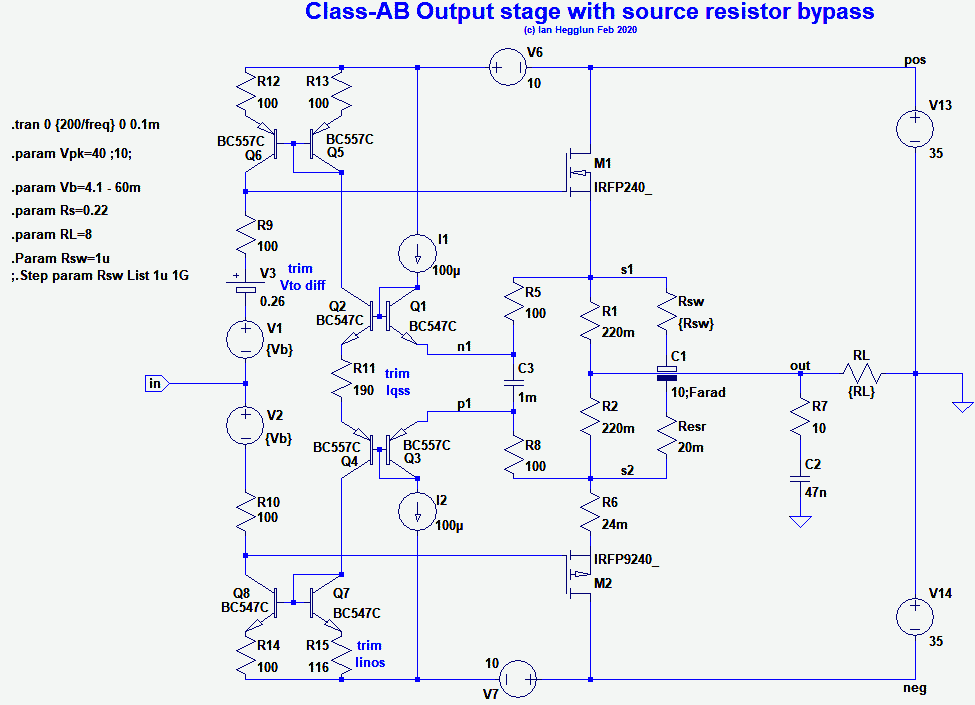
Trim R11 for the bootstrap gain (~0.9).
Trim R15 for mirror symmetry (nulls out input current offset).
None of these are critical adjustments with trimpots assuming additional stages are used. For a no global feedback amp at least one trimpot or a servo will be needed to trim out the output offset voltage.
Attachments

I shorted Source resistors on my APEX FH9 XRK mod build and I am happy to report the improvement in subjective performance. The relaxed quality of HexFets remains but with better clarity and transparency which was lacking with the Source resistors. With the source resistors the sound was somehow smeared. I was pleasantly surprised. Based on this experience I intend to omit source resistors from all my Hexfet builds especially because I never build anything with more than one pair of output transistors.

It does seem to solve the issue, which is good, but it requires several layers of additional complexity, which makes it moderately attractive.Following Post 57 here's an implementation of bootstrapping to remove the supercapacitor displacement with varying power levels.

Trim R11 for the bootstrap gain (~0.9).
Trim R15 for mirror symmetry (nulls out input current offset).
None of these are critical adjustments with trimpots assuming additional stages are used. For a no global feedback amp at least one trimpot or a servo will be needed to trim out the output offset voltage.
A full Iq servo would probably have a comparable level of complexity, and have a better, more deterministic control over the Iq without emitter/source resistors
- Home
- Amplifiers
- Solid State
- Emitter resistor in HexFet OPS