Color coordination
Zero D ,
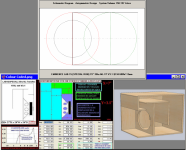
Ok , i went ahead and made color coded rectangles around the Hornresp input sections that correspond with the color coded sketch above the inputs screenshot...
I can still do arrows if you like, but they might look a bit messy ....
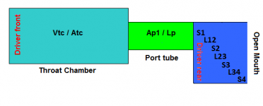
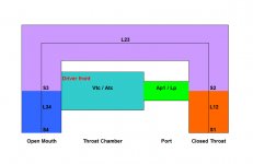
You can see that the majority of the box is just a giant throat chamber (Vtc/Atc), which is colored with aqua .... The duct or mass loading (Ap1/Lpt) is in green ........ and the front chamber and mouth (in periwinkle) are composed of S1-S4 which only counts for 40cm total at best depending on how you want to look at it , some might argue that it should count for less (maybe about 20cm total) but either way it works, so all is well 🙂 This is a very unorthodox arrangement for Hornresp but valid nonetheless ...
.
Hi, could you please show how you Actually translated the HR sim, into the drawings. Because from just the sim, i can't work out you got there 🙁
If you would, i would find it Extremely helpful if you drew in arrows from each part of the sim which corresponds with the folds/areas.
Thanx in advance 😉
Zero D ,
Ok , i went ahead and made color coded rectangles around the Hornresp input sections that correspond with the color coded sketch above the inputs screenshot...
I can still do arrows if you like, but they might look a bit messy ....
You can see that the majority of the box is just a giant throat chamber (Vtc/Atc), which is colored with aqua .... The duct or mass loading (Ap1/Lpt) is in green ........ and the front chamber and mouth (in periwinkle) are composed of S1-S4 which only counts for 40cm total at best depending on how you want to look at it , some might argue that it should count for less (maybe about 20cm total) but either way it works, so all is well 🙂 This is a very unorthodox arrangement for Hornresp but valid nonetheless ...
Attachments

Zero D ,
Ok , i went ahead and made color coded rectangles around the Hornresp input sections that correspond with the color coded sketch above the inputs screenshot...
I can still do arrows if you like, but they might look a bit messy ....
You can see that the majority of the box is just a giant throat chamber (Vtc/Atc), which is colored with aqua .... The duct or mass loading (Ap1/Lpt) is in green ........ and the front chamber and mouth (in periwinkle) are composed of S1-S4 which only counts for 40cm total at best depending on how you want to look at it , some might argue that it should count for less (maybe about 20cm total) but either way it works, so all is well 🙂 This is a very unorthodox arrangement for Hornresp but valid nonetheless ...
Hmmm I think I might make a version of this for my car.
I was going to use a JBL 18", but Art pointed out that the xmax on the driver isn't so hot. And I have an Alpine SWS-15D2 that's been collecting dust in my storage unit. IIRC, the Alpine has the following advantages:
1) it has more displacement than the LAB-15
2) it has smaller VAS, reducing the box requirements
3) it has dual 2ohm voice coils, which makes it a nice match for stereo car amps
4) it has about as much displacement as my JBL 18, by virtue of it's larger xmax
hmmmm...
I'll throw together a hornresp model and post the results
@ Matthew Morgan J
Hi, i'm still having difficulty in translating the Actual HR sim diagram into what you drew ? If you could add in arrows as you kindly offered, which go from each section of Your drawing to each corresponding section in the HR sim, that would be Immensely helpful.
Regards
@ Patrick Bateman
Looking forward to that too 🙂
Attachments
i'm still having difficulty in translating the Actual HR sim diagram
Hi Zero D,
I have to give you full marks for persistence 🙂.
The dashed red circle in the Hornresp schematic diagram represents the front side of the driver diaphragm, facing into the horn throat chamber. The throat chamber has a volume of Vtc and a cross-sectional area of Atc. For the given design, Atc has almost the same value as Sd, which is why a separate circle showing an "end-on" view of the throat chamber cannot be seen in the Hornresp schematic diagram.
The smaller dashed black circle inside the red dashed circle in the Hornresp schematic diagram represents an "end-on" view of the port or duct connecting the throat chamber to the horn proper. The port has a cross-sectional area of Ap1 and a length of Lp.
The dashed green circle in the Hornresp schematic diagram represents the rear side of the driver diaphragm, facing into the horn mouth. The acoustic path from the centre of the port exit to the centre of the rear side of the diaphragm is given by L23.
Attachment 2 shows a "side-on" view of the throat chamber and port.
The design, while certainly innovative in its use of a relatively large throat chamber and port, should be interpreted in exactly the same way as any other tapped horn. The input parameters still have the same meanings as before. Attachment 3 is an attempt to show this. The sound from the front side of the driver diaphragm travels through the throat chamber shown coloured in aqua, through the port shown coloured in green, and then back down the horn path shown coloured in periwinkle.
I will leave it for you to decide how closely the simulation model approximates the proposed physical layout.
Kind regards,
David
Attachments


Yes , What Mr McBean said ^
Fantastic explanation David !
Thank you for taking the time to go into the details of it .. 🙂
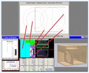
I took a few minutes to look at the new graphic that you made, then i loaded it into an editor and made a remix of it trying to imagine how it would look in Hornresp if the throat chamber and duct were fully depicted in the main diagram ... I just wanted to show this to you to see if you thought it could be another way to represent it as a schematic diagram in the style and terminology of Hornresp ... I know that "driver rear" should probably be represented by a circle and maybe i should change the front chamber/mouth to a periwinkle color in order to match the old build sketch but other than that what do you think of this?
Fantastic explanation David !
Thank you for taking the time to go into the details of it .. 🙂
I took a few minutes to look at the new graphic that you made, then i loaded it into an editor and made a remix of it trying to imagine how it would look in Hornresp if the throat chamber and duct were fully depicted in the main diagram ... I just wanted to show this to you to see if you thought it could be another way to represent it as a schematic diagram in the style and terminology of Hornresp ... I know that "driver rear" should probably be represented by a circle and maybe i should change the front chamber/mouth to a periwinkle color in order to match the old build sketch but other than that what do you think of this?
Attachments
Last edited:
Hmmm I think I might make a version of this for my car.
I was going to use a JBL 18", but Art pointed out that the xmax on the driver isn't so hot. And I have an Alpine SWS-15D2 that's been collecting dust in my storage unit. IIRC, the Alpine has the following advantages:
1) it has more displacement than the LAB-15
2) it has smaller VAS, reducing the box requirements
3) it has dual 2ohm voice coils, which makes it a nice match for stereo car amps
4) it has about as much displacement as my JBL 18, by virtue of it's larger xmax
hmmmm...
I'll throw together a hornresp model and post the results
Patrick ,
I really like the T/S parameters and capabilities of some of the Alpine drivers , the pricing is reasonable on those as well
 ... My early attempts at this ML-Transflex design (a smaller version) were built around a 10" Alpine which had ideal parameters for the design, unfortunately that driver is no longer available but some of the Type-S series look like affordable options!...
I remember simulating a number of different drivers in this 150L ML-Transflex tuned to 35hz . The Dayton PA385s-8 looked particularly good ..
Originally Posted by David McBean
I have to give you full marks for persistence 🙂.
Hopefully it's paying off 😀
Thanx VERY much for the sketches & info etc 🙂 I'll study & tinker further 😉
@ Matthew Morgan J
Thanx a lot also to to you 🙂 I hope David will look into your suggestion as well. Whatever can be done to make the translation easier/better, will benefit Everyone. Plus more people will then be able to Actually sim & then Produce different types of enclosures, not just 1 or 2
@ David McBean
Hi, generally a little progress i think !
I hadn't, realised until now, that the horizontal layout of the segments were Directly associated with the other items on the same line, Duh !
And that L12 = Length of 1 -> 2, L23 = Length of 2 -> 3, L34 = Length of 3 -> 4, L45 = Length of 4 -> 5 Duh ! The help file doesn't Directly state these things, though it does show a dashed etc layout.
*
With regard to MMJ's design. If i move my mouse All around the Schematic Diagram, i ONLY see 4 items get highlighted with RED descriptions, not all areas/things etc ?
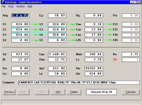
Also L12/L23/L34 are Not listed/adjustable in the Input Parameters, only in the Loudspeaker Wizard ? But L45 is listed/adjustable in the Input Parameters.
With just these few examples, i hope you are able to see why some of us can find some of it confusing etc.
Hi, generally a little progress i think !
I hadn't, realised until now, that the horizontal layout of the segments were Directly associated with the other items on the same line, Duh !
And that L12 = Length of 1 -> 2, L23 = Length of 2 -> 3, L34 = Length of 3 -> 4, L45 = Length of 4 -> 5 Duh ! The help file doesn't Directly state these things, though it does show a dashed etc layout.
*
With regard to MMJ's design. If i move my mouse All around the Schematic Diagram, i ONLY see 4 items get highlighted with RED descriptions, not all areas/things etc ?
Also L12/L23/L34 are Not listed/adjustable in the Input Parameters, only in the Loudspeaker Wizard ? But L45 is listed/adjustable in the Input Parameters.
With just these few examples, i hope you are able to see why some of us can find some of it confusing etc.
Attachments
I just wanted to show this to you to see if you thought it could be another way to represent it as a schematic diagram in the style and terminology of Hornresp
Hi MMJ,
Thanks for suggesting the alternative schematic diagram representation.
The schematic diagram layout used in Hornresp for offset driver and tapped horns was chosen because it enables systems to be drawn to scale, and for axisymmetric horn segment flare profiles to be accurately shown. As far as I can see, it would not be possible to do this with any other drawing arrangement. If in doubt interpreting the schematic, the exported AkAbak script nodal network diagram can be studied to help in understanding the acoustic path through the system.
With regard your suggested alternative schematic, the problem as I see it is really needing to know what layout the user has in mind before being able to construct the drawing as shown 🙂.
I think that in the case of your very clever design, interpreting the Hornresp schematic perhaps becomes a bit more problematic for users because L12 is very short at 1 mm, the throat chamber and associated port are relatively long, and Atc is very close in value to Sd, masking the presence of the throat chamber in the schematic. That's why it becomes necessary to check the specified dimensions to understand exactly what is intended, and to realise that the throat chamber and port must actually be folded for a practical design to work, given the "short" 23 cm length specified for L23.
Kind regards,
David
Hi Zero D,
No wonder you were confused 🙂.
The Help file does say that S1 is the throat area of horn segment 1, S2 is the mouth area of horn segment 1, and that L12 is the axial length of horn segment 1. Not sure how it can be explained more clearly. I didn't see the need to repeat the information for the other three segments as I thought it should be obvious. I did however give a clue by saying that S2, as well as being the mouth area of horn segment 1, was also the throat area of horn segment 2. The Multiple Segment Horn "layout drawing" brings it all together by showing the complete picture for all four segments.
The Help file also states: "Moving the mouse pointer over an object or message on the input parameters window displays a context-sensitive explanatory note in the status bar panel at the bottom of the window". Surely this is sufficient?
You will see descriptions for all "things" on the schematic, but no details of cross-sectional areas or axial lengths are included because they are given on the main input parameters screen. I did not want the schematic diagram to become unnecessarily cluttered with information readily available elsewhere.
All fields on the input parameters screen that are not disabled when in Edit mode, can be changed / adjusted. The L12, L23, L34 and L45 labels are only shown when a segment is unused, otherwise the user-specified flare profile for that segment will be displayed.
Perhaps it's a good time to re-read the Horn Parameters section in the Hornresp Help file, or to Google 'Hornresp tutorials' 🙂.
Kind regards,
David
I hadn't, realised until now, that the horizontal layout of the segments were Directly associated with the other items on the same line,
No wonder you were confused 🙂.
And that L12 = Length of 1 -> 2, L23 = Length of 2 -> 3, L34 = Length of 3 -> 4, L45 = Length of 4 -> 5 Duh ! The help file doesn't Directly state these things, though it does show a dashed etc layout.
The Help file does say that S1 is the throat area of horn segment 1, S2 is the mouth area of horn segment 1, and that L12 is the axial length of horn segment 1. Not sure how it can be explained more clearly. I didn't see the need to repeat the information for the other three segments as I thought it should be obvious. I did however give a clue by saying that S2, as well as being the mouth area of horn segment 1, was also the throat area of horn segment 2. The Multiple Segment Horn "layout drawing" brings it all together by showing the complete picture for all four segments.
The Help file also states: "Moving the mouse pointer over an object or message on the input parameters window displays a context-sensitive explanatory note in the status bar panel at the bottom of the window". Surely this is sufficient?
With regard to MMJ's design. If i move my mouse All around the Schematic Diagram, i ONLY see 4 items get highlighted with RED descriptions, not all areas/things etc ?
You will see descriptions for all "things" on the schematic, but no details of cross-sectional areas or axial lengths are included because they are given on the main input parameters screen. I did not want the schematic diagram to become unnecessarily cluttered with information readily available elsewhere.
Also L12/L23/L34 are Not listed/adjustable in the Input Parameters, only in the Loudspeaker Wizard ? But L45 is listed/adjustable in the Input Parameters.
All fields on the input parameters screen that are not disabled when in Edit mode, can be changed / adjusted. The L12, L23, L34 and L45 labels are only shown when a segment is unused, otherwise the user-specified flare profile for that segment will be displayed.
With just these few examples, i hope you are able to see why some of us can find some of it confusing etc.
Perhaps it's a good time to re-read the Horn Parameters section in the Hornresp Help file, or to Google 'Hornresp tutorials' 🙂.
Kind regards,
David
Thanx VERY much for the sketches & info etc 🙂 I'll study & tinker further 😉
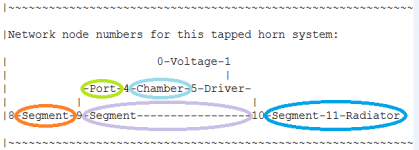
Note that attachment 3 in post #185 above shows essentially the same information as the exported AkAbak script nodal network "acoustic path" diagram previously posted in the Hornresp thread - just presented in a different form.
Attachments
AHA
Ok , i see it now,
David, with that color coded schematic from #185 and #192, the part that was throwing me off was the long L23 section which in that depiction is proportionately larger than the Throat chamber and that seemed confusing to me at first but now i understand it had to be drawn that way to make the schematic work ... This was not meant to be a proportionate schematic , i get it now 🙂 .... You employed two new colors , Orange is duct exit offset (instead of driver offset) , and that nice dark blue is more or less the mouth right? If the schematic was meant to be proportionate the orange section would be very small , only a sliver ...
Am i interpreting this schematic diagram correctly now?
Note that attachment 3 in post #185 above shows essentially the same information as the exported AkAbak script nodal network "acoustic path" diagram previously posted in the Hornresp thread - just presented in a different form.
Ok , i see it now,
David, with that color coded schematic from #185 and #192, the part that was throwing me off was the long L23 section which in that depiction is proportionately larger than the Throat chamber and that seemed confusing to me at first but now i understand it had to be drawn that way to make the schematic work ... This was not meant to be a proportionate schematic , i get it now 🙂 .... You employed two new colors , Orange is duct exit offset (instead of driver offset) , and that nice dark blue is more or less the mouth right? If the schematic was meant to be proportionate the orange section would be very small , only a sliver ...
Am i interpreting this schematic diagram correctly now?
Last edited:
Hi MMJ,
Correct. The colour-coded diagram is not drawn to scale. As mentioned in Post #190, that's why the Hornresp schematic is the way that it is, so that the system can be displayed accurately proportioned.
Correct. Horn segment 1 is coloured orange and horn segment 3 is coloured dark blue, with S4 being the open mouth of horn segment 3. Note that in your design the position of the mouth opening relative to the driver is a bit different to that in the simulation model, but it shouldn't affect the overall results too much. The attachment below shows the difference in mouth positions.
Correct. If drawn to scale, the length of the orange section L12 would be very small at 1 mm. In the Hornresp schematic diagram itself, horn segment 1 is only just visible. (S1 is at the vertical black solid line, and S2 is at the vertical red dotted line immediately to the right of the black line).
Yes 🙂.
Incidentally, hopefully it is obvious from the colour coding, but one thing I meant to clarify in Post #192 is that the nodal network diagram shows the system reversed to the way it is presented in the colour diagram. Both are accurate representations, just drawn differently.
Kind regards,
David
the part that was throwing me off was the long L23 section which in that depiction is proportionately larger than the Throat chamber and that seemed confusing to me at first but now i understand it had to be drawn that way to make the schematic work ... This was not meant to be a proportionate schematic
Correct. The colour-coded diagram is not drawn to scale. As mentioned in Post #190, that's why the Hornresp schematic is the way that it is, so that the system can be displayed accurately proportioned.
Orange is duct exit offset (instead of driver offset), and that nice dark blue is more or less the mouth right?
Correct. Horn segment 1 is coloured orange and horn segment 3 is coloured dark blue, with S4 being the open mouth of horn segment 3. Note that in your design the position of the mouth opening relative to the driver is a bit different to that in the simulation model, but it shouldn't affect the overall results too much. The attachment below shows the difference in mouth positions.
If the schematic was meant to be proportionate the orange section would be very small, only a sliver
Correct. If drawn to scale, the length of the orange section L12 would be very small at 1 mm. In the Hornresp schematic diagram itself, horn segment 1 is only just visible. (S1 is at the vertical black solid line, and S2 is at the vertical red dotted line immediately to the right of the black line).
Am i interpreting this schematic diagram correctly now?
Yes 🙂.
Incidentally, hopefully it is obvious from the colour coding, but one thing I meant to clarify in Post #192 is that the nodal network diagram shows the system reversed to the way it is presented in the colour diagram. Both are accurate representations, just drawn differently.
Kind regards,
David
Attachments

Hey David, with those mouth exits in 2 different locations, is L34 still the same length?
Hi BP1Fanatic,
I very much doubt it 🙂.
Any deviation from the configuration assumed by the standard simulation model unfortunately muddies the waters quite nicely 🙂.
Kind regards,
David
Originally Posted by David McBean
No wonder you were confused 🙂
Indeed 😀
Well Thanx to you & Matthew Morgan J things are clearer now 🙂
You will have noticed that, several other people more experienced than me with HR, have also not been sure of a number of things recently 😉
Keep up the good work, & Anything you can do that makes things easier etc, Will be Most welcome, to me & Lots of others too 🙂
Good stuff!
Oh yes, THIS HAS BEEN SUCH A GREAT EXCHANGE!!!
I fully appreciate the explanations and sketches that David took the time to put together for us ... THANK YOU DAVID!!!! I am definitely going to add some of this information to my ML-Transflex folder so that it can shared with anyone in the future who may have questions about the design or how it translates from Hornresp.
Also big Thanks to Zero D for putting so much effort into trying to understand this design, and asking the right questions, that effort seemed to inspire David to come up with great explanations which can now be utilized as a reference for anyone else who may be curious!
Last edited:
@ Matthew Morgan J
I appreciate your kind words & assitance 🙂 I'm glad i persisted, as not only has it helped me, but obviously you as well 😉 Plus i expect many others too, even though they havn't posted 😛
David McBean naturally knows HR upside down & inside out, & sometimes i think he overlooks the fact that not everybody can easily translate the schematics into feasable drawings to consider building, or even learning from. The learning must come before considering Any building, so if we can't Totally make sense of the translation/s, we can go no further. Which is a Great pity, as the program is capable of doing so much. That's why whatever can be done to make it more intuative, to as many people as possible, is a win win all round 🙂
sometimes i think he overlooks the fact that not everybody can easily translate the schematics into feasable drawings to consider building, or even learning from.
You underestimate me. At all times I am acutely aware that the education / knowledge / experience / skill levels of Hornresp users and therefore their comprehension and understanding of Hornresp, vary considerably.
The Hornresp axisymmetric schematic diagram was never intended to be a construction drawing - that's why it is quite deliberately called a schematic.
From the Oxford Dictionary - Schematic: (Of a diagram or other representation) symbolic and simplified.
The aim of the Hornresp schematic "drawn to scale" diagram is simply to show how all the components making up the specified loudspeaker system are interconnected acoustically. Only the user knows how the system is to be physically configured and built. This is clearly evidenced by MMJ having to produce his colour-coded drawing so that we all knew what he had in mind, and how the various acoustic components making up his system were to be folded.
If you can think of a better way to present the Hornresp scaled schematic diagram, in particular for offset driver and tapped horn systems, then I would be very interested in your ideas.
Which is a Great pity, as the program is capable of doing so much. That's why whatever can be done to make it more intuative, to as many people as possible, is a win win all round
If you are having difficulty in understanding the features available in Hornresp then try reading the Help file carefully, and thinking about what the information contained in the file is actually telling you. The fact that you hadn't realised until recently that "the horizontal layout of the segments were directly associated with the other items on the same line" would suggest to me that perhaps you hadn't actually used Hornresp very much, and / or that you had not read / understood what the Help file was telling you.
If you are having difficulty interpreting the schematic diagram, then try changing the parameter values in the Loudspeaker Wizard to see what parts are affected. This will help you to understand what it all means.
- Status
- Not open for further replies.
- Home
- Loudspeakers
- Subwoofers
- Eminence LAB15 Subwoofer, 4ohm, Special Run for CHEAP on ebay