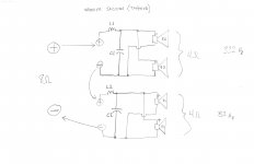
Gentlemen, I have a really good question about passive crossovers. I need to mix 2 parallel filters into one series filter in order to lower the inductor values and reach the low pass cut-offs. I'm building a center speaker with 4 drivers for the bass section. It is a 3.5 way. Two primary woofers will be from 20 to 330 Hz and the two outer will be tapered down to 80 Hz. Attached is my quick Xover sketch for better explanation. I'd like to know if this is possible and what influence will the two parallel sections will have on each other when connected in series. The goal here is to maintain 8 ohms for the amp. The woofer impedance is 8 Zohms.
Attachments
The general shape looks a lot like mine. Do you have any other pictures showing driver placement etc?
Spheres aren't a big problem once I get my CNC mill operational. Might be worth looking into.
Hi novec,
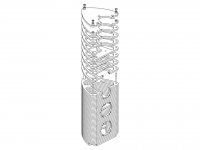
The TAD1 stacked translam speaker construction is one good reason to own a CNC mill instead of just a table saw. An MDF build might have acceptable cost. In addition to well rounded edges, irregular back wave disruptor protrusions, and optimal cross bracing, some designers include cavities for sand to dampen vibrations. It would also seem easy to build-in a cavity for a crossover or the round overs for the entry+exit of a tube port, or to make an interesting base with a port exit similar to B&W designs.
Pictures did not post in last message.
For a sphere with a tapered tube I wonder if using a concrete sculpture mix (concrete + sand + fiberglass strands + latex liquid) plus some chicken wire shaped over a basketball might be a good summer project. Cover the basketball and rear tube with plastic wrap. Deflate the basketball and pull it out when the concrete is dry.
For a sphere with a tapered tube I wonder if using a concrete sculpture mix (concrete + sand + fiberglass strands + latex liquid) plus some chicken wire shaped over a basketball might be a good summer project. Cover the basketball and rear tube with plastic wrap. Deflate the basketball and pull it out when the concrete is dry.
Attachments
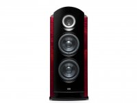
That's probably the one I'm thinking of. Nice looking thing, and not exactly cheap... I'm still not entirely sure whether to go for "full sandwich" like the TAD1 or the semi-sandwich with separate walls and more conventional bracing like in the pics I attached earlier.
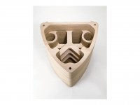
The main argument for the separate approach is that separate bracing over the full length of the wall is better than a few crossbars, but I don't necessarily agree. Neither does TAD 🙂 I'm imagining that the strength that comes from keeping the wall and supporting structure as one continous part, thus eliminating any flex in the joint between wall and brace, outweighs the lack of support on the open layers.
There will be far more strength in the glue joints between layers than those between wall and brace, both because of the vastly larger surface area and because the glue joint will only see shear forces, not actual pull. What to do...
Any oppionions on mixing materials? For example using plywood for bracing and MDF for the rest, or alternating every layer. I'm just thinking that might give the best of both worlds.
DRAWING SOFT.... & MILLING HARDWARE
Hello novec,
What software do You use for drawing Yours design and how do You intend
to interact the final design phase with Yours milling hardware You once mentioned & intend to use for this project ? 🙄
Regards
C. B.
Hello novec,
What software do You use for drawing Yours design and how do You intend
to interact the final design phase with Yours milling hardware You once mentioned & intend to use for this project ? 🙄
Regards
C. B.
- Status
- Not open for further replies.
- Home
- Loudspeakers
- Multi-Way
- Elliptical enclosure - reflection/diffraction issues?