I recently had to make a number of extremely low level measurements, to evaluate the performance of the Nonoiser, and to test the X10 transformers (one physical and the other virtual) to enhance the sensitivity of my LNA.
One of the most difficult issue was the pervasive presence of 50Hz magnetic field + harmonics.
I had to resort to notch filters and digital filtering techniques to arrive at a not too polluted level.
I tried magnetic shields, but the field induces parasitic emf's in the test cabling, in particular the grounds, meaning there is a huge area to cover.
Now, I have experimented with an active shield, that counteracts the stray AC fields with an opposite drive.
The principle is well-known, but here it is a bit peculiar: both the sensor and actuator are simple coils, which is easy and cheap, but presents a number of challenges.
The setup necessarily operates in a closed-loop fashion, and stabilizing the whole thing for a useful frequency range is not an easy task: there are multiple poles to take into account, not only at the top of the spectrum, but also in the VLF region because the system does not pass DC, obviously.
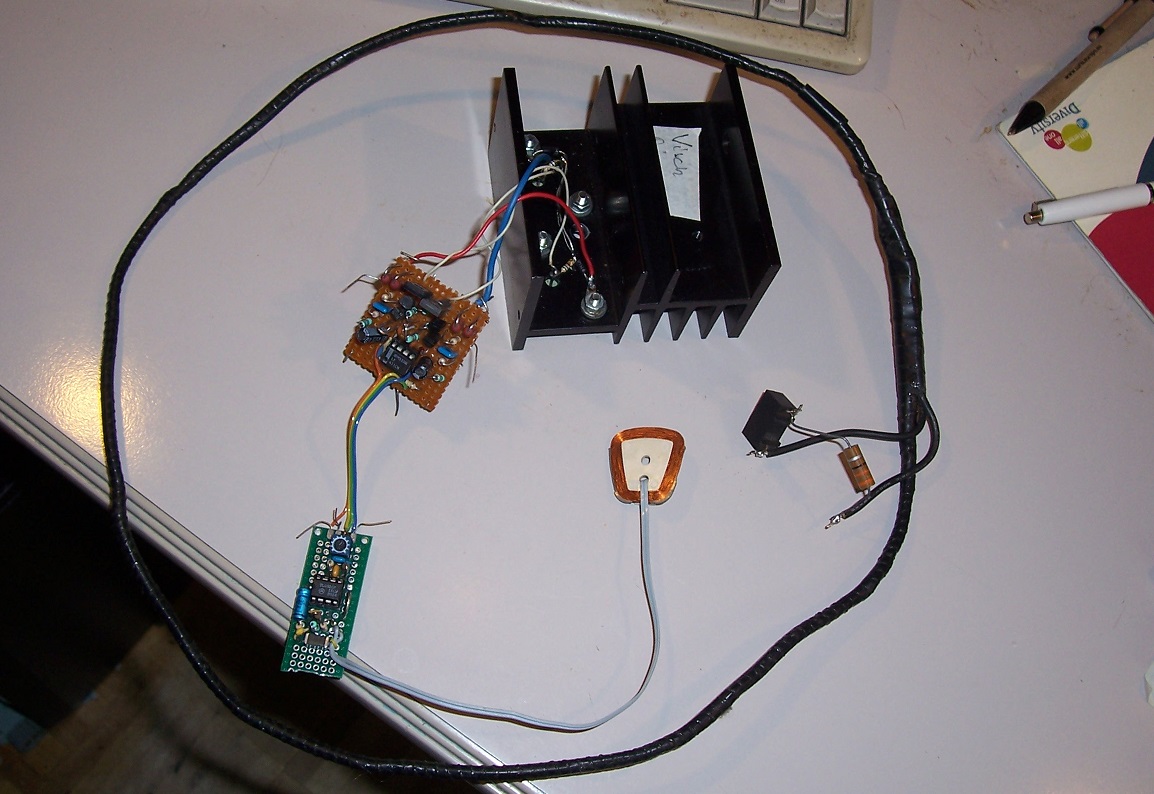
As I hate to wind my magnetic components myself, I reused ready-made coils: the sensor is from the actuator of a HDD, and the drive coil is a degaussing harness from an old CRT monitor:
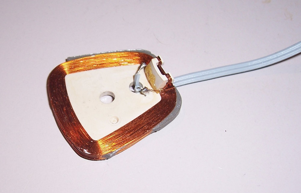
I measured the electrical and magnetic parameters of both: the sensor has an inductance of 950µH, a DC resistance of 8.2 ohm and a // capacitance equivalent to 18.5pF.
The degaussing loop has an inductance of 770µH and a resistance of 2.5 ohm.
The coupling coefficient is ~0.0056.
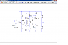
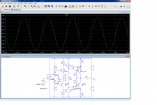
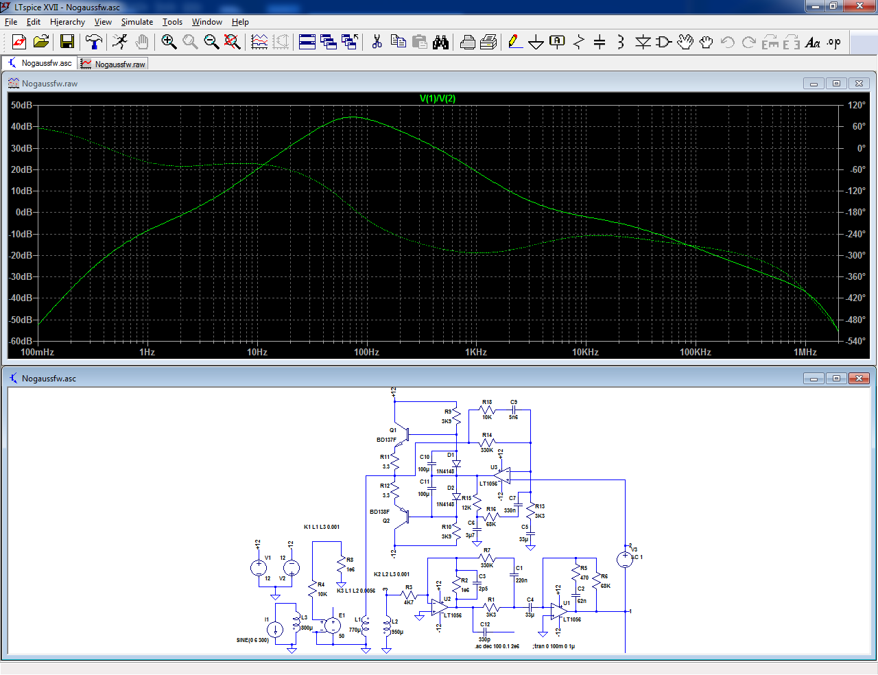
Here is the concept:
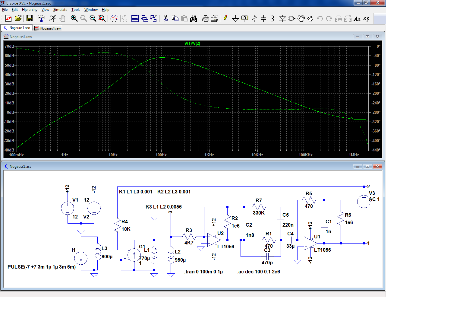
L1 is the drive coil, L2 is the sensor, and L3 generates the perturbating field.
The conditioning circuit is an integrating error amplifier, driving a transamp symbolized by G1.
Of course, this is only 1/3rd of a complete shielding system: you need two identical channels for the Y and Z axis, and if you want to do things really properly, a total of 6 drive coils in a Helmotz configuration is required
The loop gain reaches ~60dB @ 100Hz, which is very substantial.
One of the most difficult issue was the pervasive presence of 50Hz magnetic field + harmonics.
I had to resort to notch filters and digital filtering techniques to arrive at a not too polluted level.
I tried magnetic shields, but the field induces parasitic emf's in the test cabling, in particular the grounds, meaning there is a huge area to cover.
Now, I have experimented with an active shield, that counteracts the stray AC fields with an opposite drive.
The principle is well-known, but here it is a bit peculiar: both the sensor and actuator are simple coils, which is easy and cheap, but presents a number of challenges.
The setup necessarily operates in a closed-loop fashion, and stabilizing the whole thing for a useful frequency range is not an easy task: there are multiple poles to take into account, not only at the top of the spectrum, but also in the VLF region because the system does not pass DC, obviously.
As I hate to wind my magnetic components myself, I reused ready-made coils: the sensor is from the actuator of a HDD, and the drive coil is a degaussing harness from an old CRT monitor:
I measured the electrical and magnetic parameters of both: the sensor has an inductance of 950µH, a DC resistance of 8.2 ohm and a // capacitance equivalent to 18.5pF.
The degaussing loop has an inductance of 770µH and a resistance of 2.5 ohm.
The coupling coefficient is ~0.0056.
Here is the concept:
L1 is the drive coil, L2 is the sensor, and L3 generates the perturbating field.
The conditioning circuit is an integrating error amplifier, driving a transamp symbolized by G1.
Of course, this is only 1/3rd of a complete shielding system: you need two identical channels for the Y and Z axis, and if you want to do things really properly, a total of 6 drive coils in a Helmotz configuration is required
The loop gain reaches ~60dB @ 100Hz, which is very substantial.
Attachments


Skeptik
I'm skeptic although the idea is good. My doubt is that your system will cancel the magnetic fields (Variable from certain frequency to some other maxima) only near the captor coil, but nothing guarantees the rest of the outer loop, still inside the degauss coil from CRT.
I'm skeptic although the idea is good. My doubt is that your system will cancel the magnetic fields (Variable from certain frequency to some other maxima) only near the captor coil, but nothing guarantees the rest of the outer loop, still inside the degauss coil from CRT.
Yes, that's why 3 axis would be required, using 3 pairs of Helmotz coils to define a volume rather than a plane.I'm skeptic although the idea is good. My doubt is that your system will cancel the magnetic fields (Variable from certain frequency to some other maxima) only near the captor coil, but nothing guarantees the rest of the outer loop, still inside the degauss coil from CRT.
I will come back on that later.
Now, let's have a look at practical problems.
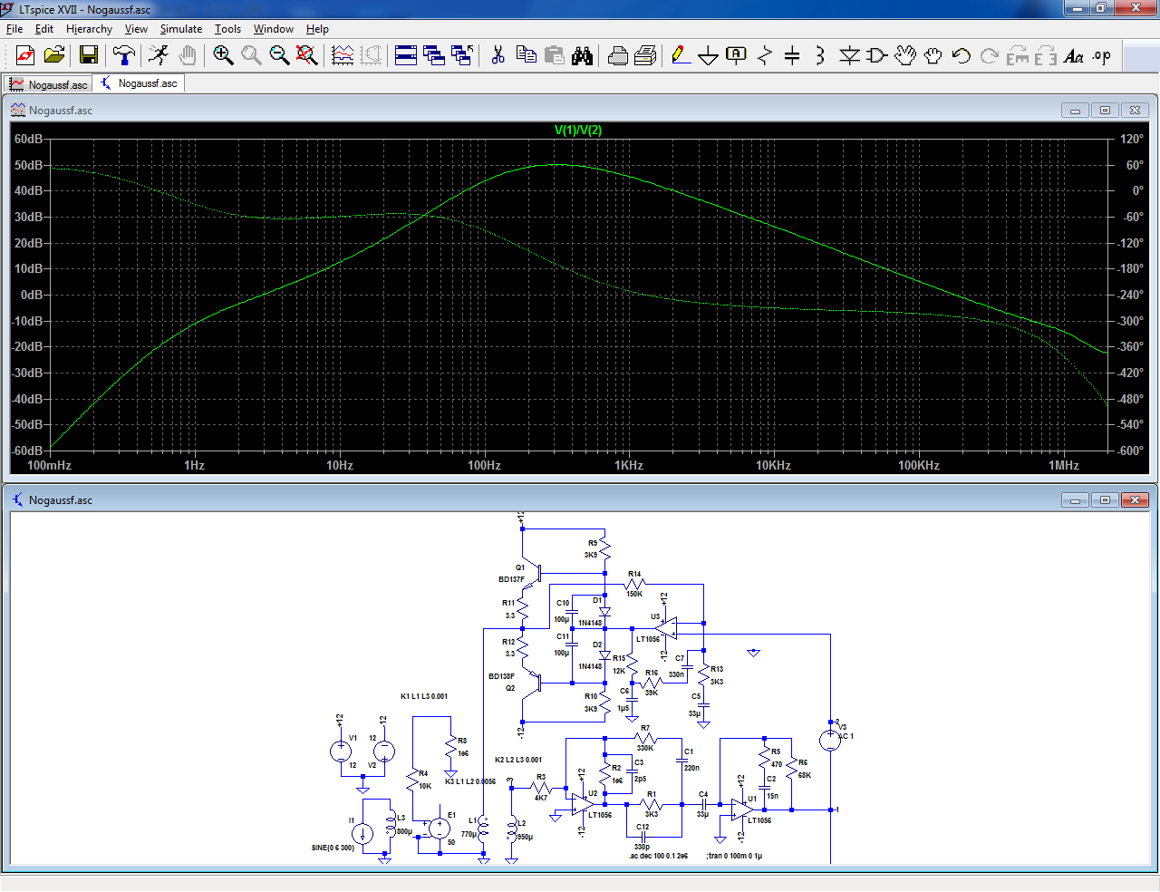
My modelling is far from perfect, and the transamp is not an idealized Spice component:
The OP transistors are 2N3055/2N3792 and the drivers BD131/132.
As I was aware that the servo loop was not going to work as easily, I included a number of mods:
I included a loop gain trimmer, and a damping network across the drive coil.
With these mods, the nogausser worked at very low gains: as soon as the wiper of the gain pot left its end stop, the amplitude of the error signal seen at the output was laminated, but pushing the gain higher lead to ~50 KHz oscillations.
I used a phase-advance cap (C1) to make the transamp more ideal, and I was able to push the gain to its maximum, without instability.
The results are impressive.
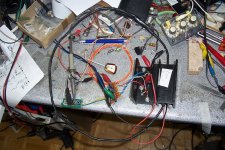
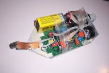
Here is the actual setup, on my test bench (messy):
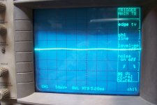
This is the signal at the output of the correction amplifier, with the transamp inactive (they are the stray field of my bench heavily amplified):
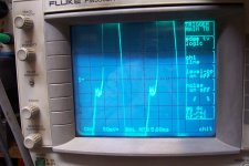
When the loop is closed, the signal looks like that (no cheat!):
So, the circuit does wonders
Attachments

Yes, with three sensor coils and six compensating coils.
Since the three axis are orthogonal, the three channels will work completely independently, and compensate any magnetic vector
Since the three axis are orthogonal, the three channels will work completely independently, and compensate any magnetic vector
I should mention that this is very much a work in progress: the basic concept does work rather well, but there is still a lot of optimization work to be carried on: for example, I vastly overdesigned the transamp.
For the correction levels required in a real environment, the transamp equivalent of a LM386 would be more than sufficient.
The way the function blocks are organized is also far from optimal: the integrating part should be last, for noise considerations.
It might be possible to merge the integrator with the transamp; that would be ideal.
And in practice, having all of the three axis might not be required for a basic compensation: if the sensor and drive coils are manually aligned with the vector direction of the perturbating field, the compensation will work.
And finally, with a large driver coil, a Helmotz configuration does not seem compulsory, because there is room for manoeuver in the plane of the driver coil.
For a 20dB background noise reduction, lots of simplifications are probably possible, and this would already be a great improvement even if it is not perfect
Alternatively build your test setup into a briefcase and take it out into a field, where ironically there won't be a field. 🙂
Thinking about it a lot of modern testgear has SMPS's, many of which will happily work at DC(*), though I've not dared try this, but it ought to be possible to avoid using an inverter when battery operated.
(*) The normal topology is filter and bridge rectifier on the input, so DC in should work nicely - of course there will be exceptions.
Last edited:
On the odd occasion, I moved to my garden, but that's not really practical.
I also have some instruments with a battery supply, and they ease somewhat ground concerns, but the vast majority of my gear is mains-supplied.
In addition, 50Hz fields are present almost everywhere: some years ago, I built a small, crude 50Hz mag field detector, and I had the surprise of being able to detect a HV power line more than half a mile away:
Attachments
Suggests a lot of current leakage from the HV circuit - they are supposed to be isolated 3-phase circuits - but I guess the neutral-ground connection at each end can unbalance them.
For 3 Helmholtz coil assemblies I guess you could mount circular coils around a cubic frame.
Found this nice picture on Wikipedia: Helmholtz coil - Wikipedia
For 3 Helmholtz coil assemblies I guess you could mount circular coils around a cubic frame.
Found this nice picture on Wikipedia: Helmholtz coil - Wikipedia
I mean real HV, (or perhaps EHV if you prefer), something like 80kV or 125kV by the look of the pylons, and the physical separation between the current-carrying conductors is sufficient to leak a significant magnetic field at considerable distances with currents of hundreds of amperes.Suggests a lot of current leakage from the HV circuit - they are supposed to be isolated 3-phase circuits - but I guess the neutral-ground connection at each end can unbalance them.
I don't think that leakage currents have something to do with this, it is the geometry and the magnitude of the currents
Yes, that is the first idea that comes to mind, and it is easily calculable, something important in 1957, but nowadays it is probably possible to adopt simpler and squarer configurations:For 3 Helmholtz coil assemblies I guess you could mount circular coils around a cubic frame.
Found this nice picture on Wikipedia: Helmholtz coil - Wikipedia
Magnetic field cancellation systems by Bilz AG
However, I think that for limited, bench-size cancellation of a particular vector (all perturbating 50Hz fields are synchronous), a twin or even single coil configuration might be sufficient
Edit: the power line in question is apparently 110kV (between Schaarbeek and Verbrande brug):
Attachments

Last edited:
I mean real HV, (or perhaps EHV if you prefer), something like 80kV or 125kV by the look of the pylons, and the physical separation between the current-carrying conductors is sufficient to leak a significant magnetic field at considerable distances with currents of hundreds of amperes.
I don't think that leakage currents have something to do with this, it is the geometry and the magnitude of the currents
Magnetic fields fall as 1/r^3, which is a pretty very dramatic fall-off. Still transmission lines carry very high currents (many kA is common, not just hundreds). You can afford several kV of IR losses in a 110kV line and the conductors are only a few ohms end-to-end.
Even 5kA only creates a few mT at a metre away.
For a ~point-like source, certainly. For a 1-dimensional source of ~infinite length, like a power line seen from a few hundreds meters, I am less sure: the 1 dimension might subtract from the d³, resulting in a 1/d² law.Magnetic fields fall as 1/r^3,
This could explain why it is detectable from such a distance.
I have now streamlined the conditioning circuit, in particular the output amp which is now a simple, buffered voltage amplifier.
The power level is much more reasonable, but is still vast overkill for correction in a quiet lab environment.
In fact, just the unbuffered opamp would probably be sufficient.
The maximum loop gain has been reduced to 50dB, which is more than sufficient.
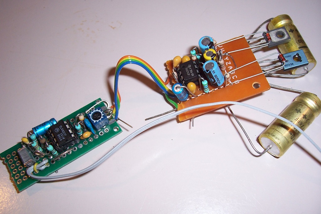
The voltage, rather than transamp amplifier inherently solves the requirement for integration.
As a result, the HF noise has been reduced, but not completely eliminated.
This was disconcerting, especially since the gain trimmer I inserted had practically no effect until it was turned down to zero.
In fact, the magnetic closed-loop system works to compensate the input noise of the front-end amplifier.
The sensor coil is so inefficient that its output with the stray fields to correct is not very much larger than the opamp's noise, leading to a poor S/N ratio.
The HF part of the gain is mostly useless in this application (correction of 50Hz and harmonics), but without elaborate compensation techniques, the gain slope needs to be 6dB/octave, starting from ~150 to 300Hz, and this allows a lot of HF noise to break in until the unity gain is reached at 180kHz.
I have tried low-noise opamps, and it improved the situation by 6~10dB, but the real solution is to opt for a more suitable sensor: more turns, and an increased area to improve the coupling and the gain.
Interesting challenges and discoveries.
The power level is much more reasonable, but is still vast overkill for correction in a quiet lab environment.
In fact, just the unbuffered opamp would probably be sufficient.
The maximum loop gain has been reduced to 50dB, which is more than sufficient.
The voltage, rather than transamp amplifier inherently solves the requirement for integration.
As a result, the HF noise has been reduced, but not completely eliminated.
This was disconcerting, especially since the gain trimmer I inserted had practically no effect until it was turned down to zero.
In fact, the magnetic closed-loop system works to compensate the input noise of the front-end amplifier.
The sensor coil is so inefficient that its output with the stray fields to correct is not very much larger than the opamp's noise, leading to a poor S/N ratio.
The HF part of the gain is mostly useless in this application (correction of 50Hz and harmonics), but without elaborate compensation techniques, the gain slope needs to be 6dB/octave, starting from ~150 to 300Hz, and this allows a lot of HF noise to break in until the unity gain is reached at 180kHz.
I have tried low-noise opamps, and it improved the situation by 6~10dB, but the real solution is to opt for a more suitable sensor: more turns, and an increased area to improve the coupling and the gain.
Interesting challenges and discoveries.
Attachments


The real remedy to the noise problem is to use a more suitable sensor coil, but I made a few simple mods to the conditioning circuit, to reduce the gain at frequencies where it is not needed.
Thanks to a second order shaping, the unity gain frequency is now ~6kHz (it was 180kHz in the previous version), and the maximum gain has barely decreased, to 45dB (and it is more accurately centered on the 50Hz~100Hz range).
If a low-noise opamp is used in U2, these mods make the circuit actually usable, but it would be simpler to use a 10mH sensor.
The drive coil could also be upgraded, as it has relatively a low time-constant creating a pole at 500Hz.
This makes the equalization to locate the gain maximum at ~50Hz difficult.
Using three times the quantity of copper would make life much easier.
Attachments
Although your efforts in the amplifier section are valuable, in my opinion the concept itself has holes in the idea. The system must respond to variation in a magnetic flux that just has occuried. You can't react immediately to such a change, because your system has time delays. So, in some instances, the degauss will response later in time, perhaps making things worse if there is a phase reversal in the main magnetic flux, duping the original flux in place of cancelling it.
Some time ago a guy here got an idea of cancelling acoustic waves capturing them with a mic and feeding this sounds amplified to a loudspeaker, but I never read that those idea could work, as acoustical waves changes in phase at impinging with surfaces, and are mostly plane waves (if the sounds came from long distances) while those you can make with a speaker are mainly spherical, or at best case, cylindrical. So never cancellation will be good, except in a very small closed volume. How small, I don't now.
IMHO you will have the same problem. But don't hesitate trying it.
The idea that feedback cannot work because the correcting action will always have some delay wrt. the perturbation is an old classic that resurfaces rather frequently, unlike the Loch Ness monster.
Agreed, any closed-loop system will always have some residual error, and the magnitude of this error will depend on the gain available, which in turn depends on factors like delay in the loop, but all of that is well known, theorized, and works well in practice.
Acoustics is more difficult, precisely because delays are very large compared to electronic circuits (and other reasons too), but magnetic fields are part of EM waves and travel at the speed of light.
It is of course difficult to make magnetic fields change quickly, but that's accounted for in the differential equations, and it is much less problematic than a pure delay.
In fact, the demonstrator I improvised works exactly as expected (like the sim). Of course, I took care to measure all the constants accurately, but once it was done, it worked perfectly (except for the noise, but this is just a dimensioning/practical problem that can be solved relatively easily).
As for the speed, the first version had a bandwidth of 200kHz, but that was vastly excessive for this application in mind and posed problems, but in case it would be needed, it would be perfectly usable, for example in the vicinity of a HF heating system, and the wideband noise would not be a problem.
The current version creates a smallish zone of perfect "magnetic silence" in the vicinity of the sensor coil, for a frequency range of 20Hz to 2KHz.
The size of the silenced zone could be increased with larger coils in a Helmhotz configuration, but the principle and the electronics would remain identical, and all this is based on sound, well-studied theories so there is no obstacle there.
What remains to be perfected are the practicalities: for example, the sensor. A coil is simple and cheap, but is not very efficient and creates unwelcome poles in the frequency response.
Commercial systems use DC-capable sensors.
Last edited:
...a guy here got an idea of cancelling acoustic waves capturing them with a mic and feeding this sounds amplified to a loudspeaker, but I never read that those idea could work, as acoustical waves changes in phase at impinging with surfaces....
Silence Please - Wikipedia
"a machine that would produce a field of absolute silence. The gadget is then used in a prank, with tragic results."
"It consisted of a microphone, a special amplifier and a pair of loud speakers. Any sound that happened to be about was picked up by the mike, amplified and inverted so it was exactly out of phase with the original noise. Then it was pumped out of the speakers, the original wave and the new one cancelled out, and the net result was silence. Of course, there was rather more to it than that. [But]... it's a simple application of negative feedback."
From Tales from the White Hart, by Arthur C. Clarke; Published by Ballantine Books in 1957
Audio Book (how ironic)
The problem with sound is that air waves run from feet to inches. You can cancel bass fairly easily, treble only in a tiny space. (Those headphones only do an inch and above 1kHz it is more cup-isolation than electronic cancellation.)
*Electric* waves are much longer, and there is no physical reason he can't cancel 20kHz and beyond over a whole room (unlike Fenton's acoustic silencer). But the devil is in the details.
Here is how I see this (potential) project:
I have no intention of building a full, 3-axis 9-coil version, capable of eliminating any parasitic field in a significant volume: it wouldn't be that complicated, because the three electronic channels can be made simply and cheaply (an opamp could in fact drive the coils directly), and the nine coils represent a pound or two of copper at most. Nothing extravagant thus, but the whole assembly would be large and cumbersome: not really practical unless you have a real need for it (and enough room to accommodate it).
I will try a single channel, non-Helmhotz version with easily movable coils.
I would first open the servo loop, and look for the average magnetic vector direction by seeking a maximum of 50Hz signal at the output of the conditioning amplifier.
I would fix the sensor coil in that position, and approximately align the driver coil in the same direction; accuracy is not needed, because it is a closed loop system, and the loop can tolerate large parameter variations.
I would then restore the FB loop, and the 50Hz field would be cancelled completely in the vicinity of the sensor.
For the harmonics, the situation would be somewhat more complex, because the relative phase of the harmonics would not necessarily be the same for all the perturbation sources (in a real environment, there will be a number of them).
This means that the vectors of the 100Hz, 150Hz, etc. will not be aligned with the coils, unlike 50Hz, and some uncorrectable errors would remain, but having the fundamental cancelled and the harmonics attenuated in a limited space would be better than nothing and could gain a few precious dB for a very limited investment in time, material and effort.
Presumably if room-temperature super-conductors existed we would just use them to make passive Helmholtz coils that would automatically cancel the field 🙂
- Home
- Amplifiers
- Power Supplies
- Eliminate your magnetic pollution with the NoGausser!!