GM, i appreciate what you mention, as well as your honesty.
I have realised that using technically correct terms helps ensure accurate communication and correct understanding of concepts, especially where students are making use of the offered material and relying on it. Besides, i do see it as a practise of self-discipline in the dedicated pursuit of the Truth.
Being technically and mathematically challenged even at 47, i prefer to use the phrase "pipe with a constant rate of expansion" to "conical". I hope the phrase is not erroneous! 😀 Conical would then be a natural subset of it.
Have a nice Sunday!
With warm regards and wishes for good health,
sujat
Agreed -I was using pure pipe physics as the example for comparing lengths of expanding & untapered, but 100% with you (and David) that in practice all these are parabolic given the parallel walls. 👍 I should have been clearer, as you say.Much belated update; I've historically mistakenly called any simple (Voigt) pipe horn as conical, but DMcB pointed out that a conical expansion where there is a parallel set of walls such as the BIB has makes it parabolic, which according to his Hornresp (HR) doesn't change the expansion audibly enough to matter in the few I checked, but IMNSHO we should still pay 'lip service' to being technically correct and wish I could 'magically' correct all mine across the WWW since going 'live' Christmas '94.
Something I don't recall checking though is if HR includes the parallel wall eigenmodes........

With reference to the linear region, even on the sunlit highlands, am pretty confident i wouldn't want Emilia Clarke to be serving drinks when she is in an unpleasant mood!! 🙂 🙏Depends where you're tuning it, since you're not obliged to use Fs -it's just the 'standard' / most common. Short version is 'potentially', but Xmax is only a quick & dirty guide to the linear operating region of the motor (definition unspecified) -it's not a mechanical limit (Xmech) or, usually, a barrier where on the one side you have Mordor (or Lancashire), and the other you have the sunlit uplands of happy cows, beaming children and Emilia Clarke serving drinks suitable to the weather & occasion (Yorkshire).
Last edited:
Was pondering over....
In case of all horns, front loaded or otherwise, provided they indeed have a sufficient (quarterwave?) axial length, is it correct to understand that they all are "fundamentally" (pun intended) quarterwave resonators at their lowest tuning frequency, while the frequency to which they (most, even in cases of exponential or tractrix rates of expansion) are acoustically coupled (impedance matched.... assuming it is a different term for the same thing) would be at least somewhat higher? To put it differently, would the exponential/tractrix horn structure too operate as a quarterwave pipe at its lowest, and as a horn only till a little/more higher up depending on how well it uses the room boundaries to increase the effective area of the terminus?
It might be practically quite difficult to achieve an effective terminus area which allows acoustic coupling down to a frequency equal to the quarterwave fundamental resonance. Is it true?
Correct, conventional horns are 1/2 WL resonators with 1/4 WL fundamentals, so only fully 'sing' an octave above Fc. From dim memory, from a given Fc, tractrix is somewhat higher IIRC.
Right, they must be 1/2 WL long for full loading, ergo in theory need a driver Fs an octave below desired gain BW, but due to tapering, using 0.707x Fs or the pioneer's Fc/1.25 works too.
For max performance though, best to reactance annul it or even my (mis)understanding of how to do it worked really well for me: rear chamber tuning mean (Fc) = (St*Fl)^0.5
That said, adding room boundary gain can dramatically shorten a large horn if built into a sufficiently rigid/massive corner.
Thank you for your generous explanation, GM.
".... but due to tapering, using 0.707x Fs or the pioneer's Fc/1.25 works too." - Would like to understand this a little more. Could you please?
".... but due to tapering, using 0.707x Fs or the pioneer's Fc/1.25 works too." - Would like to understand this a little more. Could you please?
Thank you for your considerateness, patience and your sincere efforts, GM. Unfortunately though, due to my limitations, this continues to remain elusive.
Perhaps an example of a driver with an Fs of 50 Hz in a BiB pipe might allow the principle (the 0.707x Fs or the pioneer's Fc/1.25) to percolate into my head!
Single wideband drivers and horn systems and indeed quite intriguing, by themselves as well as together!
Perhaps an example of a driver with an Fs of 50 Hz in a BiB pipe might allow the principle (the 0.707x Fs or the pioneer's Fc/1.25) to percolate into my head!
Single wideband drivers and horn systems and indeed quite intriguing, by themselves as well as together!
I have two more questions after a bit of pondering over it all:
1. How close does the ceiling need to be to the upward firing terminus in order to be most beneficial?
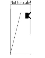
2. In case of a layout as shown in the diagram attached - the throat beginning at the rear bottom and the terminus firing forward at the bottom - are there any disadvantages (besides a marginal reduction in efficiency) to placing the driver at about 0.6 or 0.666 of the pipe's axial length?
Thanks in advance!
1. How close does the ceiling need to be to the upward firing terminus in order to be most beneficial?
2. In case of a layout as shown in the diagram attached - the throat beginning at the rear bottom and the terminus firing forward at the bottom - are there any disadvantages (besides a marginal reduction in efficiency) to placing the driver at about 0.6 or 0.666 of the pipe's axial length?
Thanks in advance!
Attachments
I'd say close, but not too close. Too far apart will cause ripples, @GM told me a few months ago, as far as I remember.1. How close does the ceiling need to be to the upward firing terminus in order to be most beneficial?
However I have to say: I don't have "golden ears" and my BIBs are ~10-15cm away from the ceiling and I don't hear much rippling going on.
Maybe it's my ears, maybe there aren't many.
Right, we ideally want to be at the pipe's end correction distance to maintain pipe loading.I'd say close, but not too close. Too far apart will cause ripples, @GM told me a few months ago, as far as I remember.
The box only loads the driver to its upper mass corner (Fhm) where T/S theory peters out, so the driver is for all intent & purposes being modulated strictly by any > 1 kHz signals and the pipe's harmonic structure that will have petered out to inaudibility as long as it's located at the optimal pipe offset:At 1KHz, probably -you'd need to do some excursion modelling yourself to know for certain, but power demands fall rapidly > 500Hz and the box load itself isn't going to significantly affect driver excursion at that frequency.
Fhm = 2*Fs/Qts'
Fs: Fhm*Qts'/2
(Qts'): (Qts) + any added series resistance (Rs)
So ideally the ceiling should be (0.61 x terminus radius) away from the terminus.Right, we ideally want to be at the pipe's end correction distance to maintain pipe loading.
Do i understand you correctly, GM?
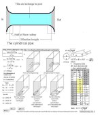
Yes, basically if yours is/are in free space, though as usual there's more to this 'story' in that we ideally need to factor in any boundary loading, so the attached chart is preferred.
Assuming yours are well away from any boundary except the ceiling, then K = 0.732 and use the math on the left side.
Assuming yours are well away from any boundary except the ceiling, then K = 0.732 and use the math on the left side.
Attachments
GM, thank you for the explanation and the chart.
Honestly, although i do get an idea of the principle that an adjacent boundary effectively extends the acoustic length of the pipe, the mathematical formulae are quite beyond my comprehension.
It was quite silly of me so far to take the "radius" as the radius of the mouth opening equivalent to the rectangular cross section of the pipe's mouth.
About the radius as shown here, how does it pertain to a pipe which has a linear rate of expansion as in a Bib?
I will certainly be putting the pipes in the corners, but with them tuned to 50 Hz, with a height of 68 inches and a ceiling which is 12.5 feet high, i doubt if there will be any useable benefit from the ceiling.
Last edited:
dude, you're overthinking :-D, i doubt if there will be any useable benefit from the ceiling.
the BiB follows the formula "more is better", if I had to describe it. It's a TQWT-esque speaker with gigantic dimensions.
You can also put the BiB on its head and put some pieces of wood under the four corners to lift the BiB up a few inches. Maybe move the speakers closer to the fold then so they're not at "knee" but at "ear level". of you Google "ibib", as in "inverted bib" you might even find the thread or pdf file on this forum. 🙂
just build the thing and have fun. I have only one bib somewhat in the corner and it's working just fine for my ears.
- Home
- Loudspeakers
- Full Range
- Elementary questions related to BiB speakers