What should be done with JP102 and JP202? I don’t have the board in front of me at the moment, but the instructions don’t mention them.
The schematic shows JP102 and JP202. Looks like tube heater feedback for voltage regulator. Should this be soldered? I don’t have the board in front of me, but remember pads for these...i think.
I have not touched those points. Clearly many of us have an issue with the TU-8600s that you are not addressing. You can blame it on our soldering or faulty tubes, but I think all the changes in the TU-8600s model has caused problems. It seems like from this thread that only certain brands of 300B tubes work with the TU-8600s model. I am trying to study the schematic and learn what is wrong with the circuit. If you don’t know what JP102 and JP202 are for, please ask the designer of the circuit, so we can get our $2000 amplifiers to work.
The designer has clearly included R225 and R125 which are populated. Those resistors do nothing unless JP102 and JP202 are connected. I was simply asking if they should be connected and why they are there.
Again, if you don’t know, please ask the designer.
The designer has clearly included R225 and R125 which are populated. Those resistors do nothing unless JP102 and JP202 are connected. I was simply asking if they should be connected and why they are there.
Again, if you don’t know, please ask the designer.
Last edited:
My board doesn’t have JP102 and JP202 although they’re in the schematic. Looks like they’re hard wired so that we always get 5.3V across the 0.47 ohm resistor and the 300B filament. Otherwise without the jumper we would get 5.7V across said resistor and 300B filament. The jumpers seem to allow selection of the filament current.
I don’t have a problem at power up, so I cannot diagnose the problem people are having, but it looks like the 12AU7 auto bias circuit maybe the culprit. I would swap the two 12AU7 tubes and see if the problem follows the tube (if the problem occurs in one channel).
I don’t have a problem at power up, so I cannot diagnose the problem people are having, but it looks like the 12AU7 auto bias circuit maybe the culprit. I would swap the two 12AU7 tubes and see if the problem follows the tube (if the problem occurs in one channel).
I have swapped the 12AU7 with known good Telefunken and EH tubes. The 12AU7 and 300B tubes I have tried all work in my rev E tu-8600. Once I am back home, I will see if my PCB has the JP102 and JP202. I just have the schematics to look at over the holidays.
You need to have cathode current through the 12AU7 to trigger the first optocoupler and some current through the 300B to trigger the second optocoupler which will turn on the cathode bias on the 300B. If either of the above conditions is not met then the channel will not power up.
My PCB does have JP102 and JP202 on side B above the 300B sockets. The PCB is labeled “TU-8600S (MP1)”
Does your have it on the reverse side? What version of PCB do you have? MP1?
Does your have it on the reverse side? What version of PCB do you have? MP1?
Just today
I already helping two diyers to finish the project. So far more than 200 pcs of TU-8600S are running
the amp is 100% ok.. 99% is the soldering issue.
You can send your PCB for repair.
The schematic does not ask you to connect JP102.. and JP202..
I will only follow the manual step by step...
I can ask two people to share their experience with you why the amp is not working... ...
Last edited:
Is there a cost for you to get the board working?
I will buy the Black Plate tubes from you to try first. You already have my email requesting to buy them on Dec. 29th
I will buy the Black Plate tubes from you to try first. You already have my email requesting to buy them on Dec. 29th
Last edited:
as long as i can help you from the web.. it is free
first send me the reference voltages..
second i want to see your soldering..
98% i can help you from the web
first send me the reference voltages..
second i want to see your soldering..
98% i can help you from the web
Elekit 8600S Build and Soldering
I received the Elekit 8600S kit for Christmas and finished it yesterday, Wednesday, December 30. I was very meticulous with the build but when I turned the amp on for the first time I only had sound out of the left channel. I talked to Victor on the phone and he was very helpful. He told me to check all my soldering and to test the voltage checks it every test point. I followed his instructions and went over my soldering at all the power connections as well as the connections for the tube sockets which take a lot of current and require a lot of solder. As soon as I did that, I put everything back together turned it on and everything worked perfectly. When Victor tells you that it’s your soldering, please trust him because he knows what he’s talking about. Also, use very high magnification glasses so that you can really see the detail of your work. This morning I tested all the voltages at the 38 test points and all of them are within spec.
I received the Elekit 8600S kit for Christmas and finished it yesterday, Wednesday, December 30. I was very meticulous with the build but when I turned the amp on for the first time I only had sound out of the left channel. I talked to Victor on the phone and he was very helpful. He told me to check all my soldering and to test the voltage checks it every test point. I followed his instructions and went over my soldering at all the power connections as well as the connections for the tube sockets which take a lot of current and require a lot of solder. As soon as I did that, I put everything back together turned it on and everything worked perfectly. When Victor tells you that it’s your soldering, please trust him because he knows what he’s talking about. Also, use very high magnification glasses so that you can really see the detail of your work. This morning I tested all the voltages at the 38 test points and all of them are within spec.
Here are the voltages. The row number is the test point number. The second column is the ideal voltage from the manual.
IMG_2134.HEIC - Google Drive
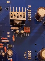
Here is a pic of the soldering:
IMG_2146.HEIC - Google Drive
Here is top side of the channel with the low voltage:
IMG_2141.HEIC - Google Drive
The ripple filter TP28 produces the correct voltage if the tubes are removed.
IMG_2134.HEIC - Google Drive
Here is a pic of the soldering:
IMG_2146.HEIC - Google Drive
Here is top side of the channel with the low voltage:
IMG_2141.HEIC - Google Drive
The ripple filter TP28 produces the correct voltage if the tubes are removed.
Last edited:
Ok
I want you check what you installed on the PCB and compare to page 13
I suspect you either install the parts in the wrong location or cold solder.
PLEASE CHEK YOU SOLDERING. EACH POINT MUST ROUND AND Circle.
Please pay attention the components
around PT 14, 12 ---> IS OPT PC201 INSTALLED OK ??. the opt affects these PT14, PT12 voltages..
I received the Elekit 8600S kit for Christmas and finished it yesterday, Wednesday, December 30. I was very meticulous with the build but when I turned the amp on for the first time I only had sound out of the left channel. I talked to Victor on the phone and he was very helpful. He told me to check all my soldering and to test the voltage checks it every test point. I followed his instructions and went over my soldering at all the power connections as well as the connections for the tube sockets which take a lot of current and require a lot of solder. As soon as I did that, I put everything back together turned it on and everything worked perfectly. When Victor tells you that it’s your soldering, please trust him because he knows what he’s talking about. Also, use very high magnification glasses so that you can really see the detail of your work. This morning I tested all the voltages at the 38 test points and all of them are within spec.
What tubes are you using?