Hello,
New member from Italy. A friend of mine purchased an Elekit TU-8100 kit from a japanese ebay vendor, instructions in japanese. He never got around to building it. He proposed to sell the kit and I accepted. He works elsewhere, so he will bring the item in a couple of weeks or so.
In the meantime have been browsing this forum and I found tons of useful information.
I have already bought two fostex full range desktop speakers, P800E, I received and assembled them. That was easy
I have no experience at all on building a vacuum tube amp. I studied on several sources online, I bought soldering kit, 0.5 mm 63/37 solder, magnifying glass with led lamp, tools. I also found a video where a Canadian man builds the amp with japanese instruction. So I studied the video.
But the instructions are in japanese. I'm a bit worried. I was wondering if some of you who built this amp could take a picture of the english instructions and private message me.
I fear that this request could come across as unfair to the north american Elekit dealer because this friend of mine bought the kit in Japan. If it is so, i do apologize. But I'm a newbie and are a little bit uneasy.
Sorry again if the request offended someone.
Regards,
Patrizio.
You may want to post on this thread. Someone there may be able to help.
https://www.diyaudio.com/community/threads/elekit-tu-8100-pcl86-integrated-amplifier.327675/
https://www.diyaudio.com/community/threads/elekit-tu-8100-pcl86-integrated-amplifier.327675/

Thanks for your replies. The video above is from a british dealer.
I had already found another video link on this forum. A member posted it on another tread.
That one is really step by step. A canadian guy builds the amp in just over two hours and that's the lenght of the video. I have already watched it twice.
This is just part one, there are four of them.
I had already found another video link on this forum. A member posted it on another tread.
That one is really step by step. A canadian guy builds the amp in just over two hours and that's the lenght of the video. I have already watched it twice.
This is just part one, there are four of them.
Last edited:
Welcome 802,
Just a few tips for new builders:
One thing I have done, specific to Elekits, is when boards are soldered 90 degrees to each other is to place short pieces across the connections before soldering. It is a bit tricky to do, help from another person is good, but eliminates a potential connection failure.
Good Luck!
Steve
Just a few tips for new builders:
- most builds fail because of poor soldering and/or rushed assembly DO NOT RUSH ASSEMBLY!!!!
- clean all of the boards and the leads of all components, sockets, etc. with methyl alcohol or isopropyl alcohol
- buy an inexpensive digital multimeter and check all of the resistors for the correct value before assembling to the boards (it is easy to mis-read the colour code)
- the electrolytic capacitors are polarity sensitive so double and triple check these are in the correct orientation before soldering.
- don't be afraid to ask questions, we were all beginners once
- if there are solder pads on both sides of the board at the tube sockets, solder both sides. This is a high-stress mechanical (therefore electrical as well) connection point
One thing I have done, specific to Elekits, is when boards are soldered 90 degrees to each other is to place short pieces across the connections before soldering. It is a bit tricky to do, help from another person is good, but eliminates a potential connection failure.
Good Luck!
Steve
Hello there,
Thank you so much. I will have the kit in a week or two, in the meantime I've been buying tools and stuff for soldering and I'm studying online how to build the amplifier.
So, to recap:
- You say I have got to clean all the boards, leads, sockets, I suppose it is before soldering. 99 degree isopropyl alcool is good? Can I buy that? Do I have to use a little brush, cotton buds, something else to clean? Do I have to clean the board also after completing the soldering?
- I will buy the multimeter for the resistors and work out how it works. In fact, I was a little bit scared of those color codes.
- I bought in Italy 63/37 solder, 0.5 millimiter, 1.8 flush. It's not the best brand around:
https://www.farinsframes.com/stagno-per-saldare-tbs-0-5-mm-100-gr/
Should I buy a better solder brand? If I've got to buy something better, is 63/37 lead solder, 0.5 millimiter good? I found the best brands very expensive, over 60 euro. Can you suggest something more affordable?
- I will take care of the orientation. I found this source online about components orientation. I suppose it is reliable:
https://www.protoexpress.com/kb/component-orientation-and-polarity/
- You talk about solder pads on tube sockets. They are those copper rings on the board, ain't they? So, if they are on both sides of a tube socket I have to sold both, right?
- As for the little boards that are fixed at 90 degree, you suggest to put short pieces across the connection before soldering. What kind of pieces, what material?
Thanks again for your help, I appreciate it.
Last edited:
Just use a paper towel with a bit of alcohol on it to wipe the boards and all component leads.
Not strictly necessary but I find things like jacks and sockets especially are more likely to have contamination on them that will make soldering more difficult.
The solder you have chosen should work fine if it is for electronic components. It is a good idea to remove extra flux from the soldered joints using a cotton swab moistened with alcohol.
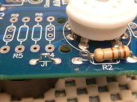
To join boards at 90 degrees use a small piece of a cut-off resistor lead bent at 90 degrees and solder it in place across the two boards at each connection point. See attached picture.
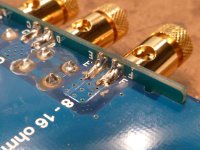
If it is possible I like to solder the tube sockets on both sides of the board. Some people only solder them on the bottom. If there is a pad on the top side of the board I like to solder there too for extra mechanical strength. See attached picture.
Not strictly necessary but I find things like jacks and sockets especially are more likely to have contamination on them that will make soldering more difficult.
The solder you have chosen should work fine if it is for electronic components. It is a good idea to remove extra flux from the soldered joints using a cotton swab moistened with alcohol.
To join boards at 90 degrees use a small piece of a cut-off resistor lead bent at 90 degrees and solder it in place across the two boards at each connection point. See attached picture.
If it is possible I like to solder the tube sockets on both sides of the board. Some people only solder them on the bottom. If there is a pad on the top side of the board I like to solder there too for extra mechanical strength. See attached picture.
Attachments
Hello,
I'm setting up a small soldering station for this first project.
I have purchased a magnifying led lamp 2X for the soldering, with a smaller 5X part. In your opinion, is 2X enough for soldering?
https://www.manomano.it/lenti-dingrandimento-3457
I read online that some use also a 10X led loupe to check the solder joints. Should I get one of these? Or do you use the same magnifyig lamp for soldering and checking? What kind of X?
Thanks in avance,

802,
If you haven't done much soldering it would be a good idea to practice a bit before you start on the boards in your kit. Get some scrap wire, twist together and solder away.
-Always keep the tip of your iron clean. Just before soldering any connections clean the tip on a damp (not soaking wet) sponge.
-Once a connection has been made, clean it again.
The old rule of thumb is the work (the connection you are soldering) should melt the solder, NOT the iron touching the work. The problem is you need to transfer the heat from the iron to the work. My preferred method is clean the tip and melt a little solder onto it. Hold the tip with solder onto the work, wait for 2 or 3 seconds for the work to heat up then melt more solder on to the connection. Once the solder has flowed smoothly on to the connection remove the iron. It is pretty straight forward with resistors, capacitors, etc. More problematic are things like tube sockets and jacks. They usually require more heat but at the same time the plastic insulation used on these components might melt. So caution is advised. It might help to melt a thin layer of solder onto these components first, though not so much that you can't get them into the holes in the boards. Using this method will generally require less "hot time" when making the final connection.
Cheers, S.
Thank you so much.
I have ordered this kit below to practice soldering. It's a pcb plus some components. It will arrive tomorrow. I will practice on this before attacking the amplifier.
https://futuranet.it/prodotto/set-di-componenti-per-imparare-a-saldare/
To clean the soldering iron I have ordered one of those brass sponges, it will arrive tomorrow. I also have one of those wet sponges. I've also got Isopropyl alcohol, tissue and a toothbrush to clean the boards before and after soldering, as you suggested.
I have been watching the video that I posted above, where a canadian guy assembles this same tu-8100 amplifier. Towards the end, for some components, he had to do some surface mount soldering. I think they were a mosfet and a voltage regulator. Those, in addition to the leads, had a flat part behind that had to be soldered on the pcb, on a square of metal. One of these components, a voltage regulator, had a hole on this flat part behind. It is impossible to see on the video how he does it. I haven't found any other video on how to solder that kind of voltage regulator. Could you advice on these surface mount components?
Your tips are most welcome,
Regards,
Last edited:
I watched the video for Britain where the FETs were soldered to the board. Be sure to clean the metal tab on the FET with alcohol. Also bend the FET leads such that the metal base contacts the the board evenly (does not spring up). It may help to have another person lightly press on the FET with a small tool or stick while you are soldering.
S.
S.
Hello there. I need some help. I got the elekit tu-8100 kit and started soldering the first pcb.
I made the first mistake, I soldered a diode upside down, with the anode lead into the katode hole. It's the diode D5.


I tried to suck the solder with a desoldering pump and most of it came away but I can't manage to get the diode out with the longnose pliers. I'm afraid of damaging the pad. What should I do? I also have some desoldering wire.
If I manage to get it out without damaging the pad, do you have any suggestion on how to keep it in place to solder it the right way?
One more thing. I had bought two cheap soldering iron. Even though I've been applying solder on the tips before and after soldering, despite having cleaned the tips with a brass sponge, they don't work anymore. The tips got already dark, probably oxidized, they refuse the solder, they get slower and slower in warming up the solder. I'm using 63/37 rosin core 0.5 mm and for both I had set a temperature of 325 Celsius.
The soldering irons are gone, I need a replacement. Could you recommend an affordable soldering iron that works well, say under 50 euro? Possibly with a normal plug and no usb. I can't spend too much
Thanks.
I made the first mistake, I soldered a diode upside down, with the anode lead into the katode hole. It's the diode D5.
I tried to suck the solder with a desoldering pump and most of it came away but I can't manage to get the diode out with the longnose pliers. I'm afraid of damaging the pad. What should I do? I also have some desoldering wire.
If I manage to get it out without damaging the pad, do you have any suggestion on how to keep it in place to solder it the right way?
One more thing. I had bought two cheap soldering iron. Even though I've been applying solder on the tips before and after soldering, despite having cleaned the tips with a brass sponge, they don't work anymore. The tips got already dark, probably oxidized, they refuse the solder, they get slower and slower in warming up the solder. I'm using 63/37 rosin core 0.5 mm and for both I had set a temperature of 325 Celsius.
The soldering irons are gone, I need a replacement. Could you recommend an affordable soldering iron that works well, say under 50 euro? Possibly with a normal plug and no usb. I can't spend too much
Thanks.
Last edited:
Here's good starter iron. Get extra tips. You'll need euro model obviously. https://www.amazon.com/YIHUA-Solder...8-1-spons&sp_csd=d2lkZ2V0TmFtZT1zcF9hdGY&th=1
You can't really cut corners with the soldering iron. For €50 you ought to be able to find a quality temperature controlled iron on an auction site or local ads. Buy good quality and you can sell it for what you paid for it.
To remove the diode, add solder, not remove it. When there is plenty of solder on the joint the heat will conduct to the other side and it is easy to pull the diode away. Then suck the solder to clean the hole.
To remove the diode, add solder, not remove it. When there is plenty of solder on the joint the heat will conduct to the other side and it is easy to pull the diode away. Then suck the solder to clean the hole.
Thanks a lot. I appreciate it. Now I know how to get out the diode.
Could you please name a couple of brands and models of reliable soldering stations?
Could you please name a couple of brands and models of reliable soldering stations?
Just like in the old days no one got fired for buying IBM, Weller isa safe bet. I have a WECP I picked up for 50€ but this looks almost identical ...
Soldering iron
Soldering iron
Try to buy this one :
https://www.ebay.it/itm/12609428289...OPGdzpeO2ObOuQbiED95PDOhcH|tkp:Bk9SR_bVxt3YYg
https://www.ebay.it/itm/12609428289...OPGdzpeO2ObOuQbiED95PDOhcH|tkp:Bk9SR_bVxt3YYg
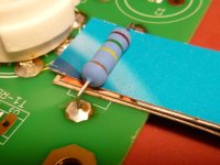
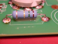
Cut the diode leads as close to the board as you can. Heat the board with your iron and remove the remainders of the leads individually. Solder short pieces of cut off resistor leads into the holes for the diode. Attach the diode to the leads as shown in the attached photo.
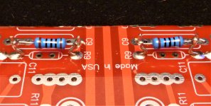
In future you may wish to space components a little bit off of the board. See attached pictures using 3 pieces of thin cardboard. Easy to remove even after soldering. Simply remove the middle piece of cardboard first. It helps with heat dissipation (and potential rework) spacing components off of the board.
S.
Attachments
- Home
- Amplifiers
- Tubes / Valves
- Elekit TU-8100 project