Hi,
I've search diyAudio and googled extensively. Tried many free tools and trials of commercial tools (SchemiIt, EasyEDA, Visio, SmartDraw, DipTrace, KiCad EDA, Sketchup, ExpressSCH and many others.
Many have tubes but they all fall short when it comes to transformer support. Others are simply overwhelming with no intuitive way to get started.
Free tools tend to be associated with PCB layout and lack of transformer support isn't surprising.
I've read that Visio has support for building transformer symbols but the Pro version required is expensive.
So how are folks producing the circuit diagrams I'm seeing in these forums?
I find Visio and Smartdraw don't make good schematics, their strengths are in office art symbols.
I would look again at KiCad, there are transformer symbols out there, but creating your own is really easy and then they will look exactly as you want
I would look again at KiCad, there are transformer symbols out there, but creating your own is really easy and then they will look exactly as you want
KiCad has transformer symbols. They are under "Device" and start with "transfo".
Plus you can draw your own symbols, either from scratch or starting with something else. there's a tutorial on the youtube.
Plus you can draw your own symbols, either from scratch or starting with something else. there's a tutorial on the youtube.
I use Vectorworks. It is a commercial CAD program and not cheap. It comes with tube symbols. I wasn't happy with them so drew my own. The same could be done with any CAD sw.
Here is a 10 year old example.
dave
Here is a 10 year old example.
dave
An eet recommended KiCad to me when i asked him to recommend pcb layout software
.:Sent by pneumatic tubes
.:Sent by pneumatic tubes
LTSpice is one of the best.
And you can use it to evaluate your circuit, and even simulate measurement of THD !
Moreover, its free.
Thanks for all the replies. I've been using LTSpice up to the driver stage to simulate a Williamson design! I didn't realise you could create a transformer like that.
I'll persevere.
Thanks for all the replies. I've been using LTSpice up to the driver stage to simulate a Williamson design! I didn't realise you could create a transformer like that.
I'll persevere.
The small secret is you don't need to create output transformer model (at least in this particular case) 🙂
Put necessary number of inductors (L1, L2, ... Ln) with inductance value in Henry, and link them with coupling factor (K1 L1 L2 ...Ln 1.0). Coupling factor 1.0 corresponds to ideal transformer with zero leakage inductance. Even with that model, results of simulation are surprisingly close to reality.
Then, if necessary, adjust coupling factor according to measured leakage inductance:
Coupling factor K = SQRT(Ls/Ls + 1)
Of course, inductance is not constant, and there are other parasitic parameters like stray capacitance, yet they are vary from one model/manufacturer to another, and with ideal model you can check problems with tube/transistor circuit alone.
I modelled Williamson upon suggestion from articles
"Improving Williamson Amplifier", Talbot Wright
"Modernize your Williamson", David Hafler
IMHO, even after tweaking, Williamson is not the best PP circuit around.
Thanks for this. You prefer the Mullard? Or are there others I'm not aware of?
While I've purchased the chokes, mains and output transformers the configuration isn't set in concrete.
While I've purchased the chokes, mains and output transformers the configuration isn't set in concrete.
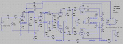
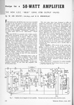
My favourite PP schematic is GEC 88-50 amplifier.
Its reasonable simple, very stable, and I've got 60W from it with very low distortions.
I have nothing against Mullard 520 derivatives, like Marantz 8, Citation II, Sansui AU111, and countless number of others.
in fact, it was first PP amp I've built.
However, I spent a lot of time fighting oscillation and instability, so I may have some prejudice against Mullards.
Attachments
Just to return to the original question for a moment. I use Visio 5 that I bought on epay for about $10. There is no need to purchase an expensive new version to draw schematics. If you have to you can create your own symbols and save them as models.
Just to return to the original question for a moment. I use Visio 5 that I bought on epay for about $10. There is no need to purchase an expensive new version to draw schematics. If you have to you can create your own symbols and save them as models.
Thanks. I have Visio Standard 2010. Since there was no Engineering template I thought I'd have no electronic symbols. I'll investigate further.
My favourite PP schematic is GEC 88-50 amplifier.
Its reasonable simple, very stable, and I've got 60W from it with very low distortions.
I have nothing against Mullard 520 derivatives, like Marantz 8, Citation II, Sansui AU111, and countless number of others.
in fact, it was first PP amp I've built.
However, I spent a lot of time fighting oscillation and instability, so I may have some prejudice against Mullards.
Thanks again. My plan was to build http://www.diyaudio.com/forums/tubes-valves/158322-my-kt88-williamson-amp-build.html as 2 monoblocks. I have the power transformer with the 80V tap now so I'll stay with that.
- Status
- Not open for further replies.
- Home
- Design & Build
- Software Tools
- Electronic diagramming tools with power and output transformer symbols