I have seen a number of amplifier schematics around that use electrolytic coupling capacitors on the input. One example is this gainclone by plastichead here http://www.plastichead.net/audioworks/redir.php?m=amps/ampmenu.htm&p=amps/other/schematics.htm
Now I always understood that the thing about electrolytics was that they are polarized and should always be biased the right way around (unpolarized electrolytics aside).
But, as a decoupling cap in such a schematic, the amplifier end is sitting at ground potential while the input end is alternating plus and minus a volt or two with the signal. So at least fifty persent of the time it is biased backwards.
Worse still the whole point of this cap is to block DC offsets on the input, which may be positive or negative, so the situation looks even worse to me.
So without any discussion of the "sound" of electrolytics (yet 🙂) how is this acceptable? Why doesn't the cap fail prematurely? What am I missing here? How did plastichead and others determine which way round the cap should go?
Thanks all.
I would guess that most people who use 'lytics as coupling caps use something like the Blackgate NX-HQ, which is actually nonpolar. While these are very good electrolytics, I personally wouldnt want them in my signal path, preferring to be DC coupled if at all possible, or using decent film caps, ideally polypropylene film-and-foil.
cetoole - I agree no caps would be best.
Apart from sonic issues, buying blackgates or large polyprops is going to double the cost of my amp judging by prices and availability in Helsinki. I'm looking to build four channels.
Now many will say I'm crazy but I would really like to put Rod Eliots active balanced receivers on these amps with nice XLR inputs. http://sound.westhost.com/project87.htm
I need to be able to reduce those caps to 1uF or less to get the price down. Or live without them which seems unwise. Or be happy with my electrolytics, which seems crazy to me just now.
By the way here is another example of electrolytic coupling caps, this time on input and output: http://users.swing.be/edwinpaij/controle_tonalite.htm
Anyone out there know how this is possible ?
if you use 2 electrolytics in series, back to back than you have made an non polarized capacitor. (at half the value) then you can put a nice capacitor 0.2 or so in parrallel with both of them.
analo_sa - A few hundred millvolts? Like may be 2 volts of my CD player output? Do you have any references for this general thinking?
neutron7 - Interesting idea. Don't we end up with a non-polarized that sounds twice as bad as a single elecrolytic?
At the moment I'm not sure I could ever hear the difference between different caps, or no cap. Guess I'll just have to try them.
neutron7 - Interesting idea. Don't we end up with a non-polarized that sounds twice as bad as a single elecrolytic?
At the moment I'm not sure I could ever hear the difference between different caps, or no cap. Guess I'll just have to try them.
A no-name filmcap will beat any 'audiophile' electrolytic as coupling cap.
Even a polyester will do it.
I know some will scream and disagree. But question is if they really go for high fidelity?
One 2.2uF polypropylene cap will do good in most audio inputs.
When input impedance (resistor from input to ground) is 10k or lower
you might want to have one 4.7uF. (or parallell two 2.2uF)
But most inputs have 22k or higher input impedance.
One of the best articles on capacitors is:
PICKING CAPACITORS
Walter G. Jung and Richard Marsh
Audio Magazine, February and March, 1980
http://www.capacitors.com/picking_capacitors/pickcap.htm
heater said:
At the moment I'm not sure I could ever hear the difference between different caps, or no cap. Guess I'll just have to try them.
i have 'heard' many bad electros.but they were really very very very very very..... bad,in construction,even the filler used was so bad 'looking'(got 4700uf/25 volts for Rs 2 each,[$1=Rs 45].
if the cap that u use is 'really' very bad(like Rs 2) then however good u may make the circuit,howsoever great n fancy cables u use etc etc,the system will sound foul.
use good caps(i use philips or panasonic),they r good,but anything fancy like $100 caps etc etc etc etc r a strict no no )for me atleast).
elctros r sturdy slugs.but avoid them for signal path(m/f or polyester r good).for large capacitances,electros r used,for small signals and faster response,look to m/f etc.
wether dc is + or -,cap blocks dc,its in its 'genes',(Xc =1/cf,f=freq,c=capacitance,Xc=capactive reactance,for dc,f=0 so Xc=infinite)
i have used pol electros in signal path without any probs,but generally they r not recommended
moreover using a 10 ohm res at i/p avoids spurious noise from entering the system(albiet at the cost of decrease in i/p level)
yup,what is audiophile cap?how does it 'sound'?it must be above $12345678900987654321? whateverA no-name filmcap will beat any 'audiophile' electrolytic as coupling cap.

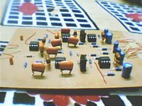
below is pic of my 12db lr xover with cap(pol electro philips at o/p[on extreme right], i/p caps r 'i-don't-know material,but value is 1uf and r non-pol[on extreme left,sitting small and isolated,orange 'dots']),,
the performance is great.
Attachments
use good caps(i use philips or panasonic), they r good,
but anything fancy like $100 caps etc etc etc etc r a strict no no )for me atleast).
elctros r sturdy slugs.but avoid them for signal path(m/f or polyester r good).
for large capacitances,electros r used,
for small signals and faster response,look to m/f etc.
In my catalog
2.2uF/100V electrolytic cap cost 1/15 of same value polypropylene
The reason for low cost is mainly, as I can think:
1. lower electrical quality
2. much lower cost to make (filmcaps are not very easy to make)
No wonder some try to sell audiophile electrolytics.
Chances to profit, make money, is good
if you can make people believe they get value for money.
Heater remember that there are two things:
DC voltage
AC voltage.
The DC voltage is very little, normally.
The AC voltage ACROSS the cap is also very little. Most of it lands across the load resistor at the intput.
DC voltage
AC voltage.
The DC voltage is very little, normally.
The AC voltage ACROSS the cap is also very little. Most of it lands across the load resistor at the intput.
Hi,
pick a 1u0F or 1u5F polyester as your input cap (much cheaper and smaller than PP).
select your input inmpedance to give the bass response you require.
I suggest 80mS to 90mS requiring Zin = 51k to 91k.
You could reduce the RC time constant at the input and raise the bass roll off frequency by 2 or 3 octaves (zin=24k to 30k) but you may find the bass somewhat lacking. Try it on one channel as an experiment.
If you must use an electro then bipolar or back to back is one method.
Method 2;- orient a polarised electro so the 600mV input offset bias is correct for the cap. Then you have 400mVac of input voltage and still no reverse bias on the electro.
A few electro manufaturers say that upto 1500mV peak is acceptable in both directions across the electro. Add this to the input offset and now 2100mVpk (1.5Vac) is your input limit.
I would recommend adding a 1u0F film bypass to the input electro.
Finally your source/s may already have DC blocking caps on their outputs. You should add those values to your amp cap value to calculate the final time constant. If you have a preamp before all these amps then think about putting a 10uF on the pre outputs with a 2m2 resistor to ground from the cap output end. To help keep the dc voltage at the pre out at true zero volts.
After reading this thread, I decided to change out the BG C electrolytics for a pair of Solen PP of the same value to see if I could detect a difference. Have to admit, I was pleasantly surprised to the change in my GC. The Solens are big and doesn't feed on the board so I had to wire them out, but the change gave improvements in many areas.
When I built my GC, I had bought a bunch of different caps for coupling. All of them are the same values but different brands ranging from Philips, Panasonics, BG, Elna RJH and the Solens. Have not managed to try them. Started with the Philips and then switched to the BG, but now with the Solens, I wonder if there is really a need to try the rest.
Great stuff guys. Thanks for the eye opener. It seems to have made a nice difference in my system.
caps
In my lm3875 briangt, Got rid of the panasonic 1500uf fc ps caps and used 200vdc 470uf computor caps there; those 2 caps per side joined by one other470 uf and took the 2 small bg 4.7uf[red] caps from the diode bridges and used them for input coupling caps. Each change made an improvement. This is the amp I am currently using lately.
In my lm3875 briangt, Got rid of the panasonic 1500uf fc ps caps and used 200vdc 470uf computor caps there; those 2 caps per side joined by one other470 uf and took the 2 small bg 4.7uf[red] caps from the diode bridges and used them for input coupling caps. Each change made an improvement. This is the amp I am currently using lately.
Attachments
heater said:But, as a decoupling cap in such a schematic, the amplifier end is sitting at ground potential while the input end is alternating plus and minus a volt or two with the signal. So at least fifty persent of the time it is biased backwards.
No, it's not.
Peranders gave you a clue, but to spell it out: When the input moves up and down with the signal, the other side of the capacitor also moves up and down with the signal. If it didn't, no signal would get through with to the input of your amplifier!
This is because the capacitor doesn't get a chance to charge up during the signal. Assuming the value of the capacitor is big enough! If it's too small, it will be able to charge during low frequency signal periods - hey presto you've made a filter! This is just one of the reasons why polarised electrolytic capacitors aren't the best choice in this application...
Worse still the whole point of this cap is to block DC offsets on the input, which may be positive or negative, so the situation looks even worse to me.
True, but in general the DC offsets encountered should be measured in millivolts, so wouldn't harm the capacitor. And looking at it the other way, often the input capacitor is used to ensure that the input end of your amplifier sees a constant DC resistance to ground or some other point….
How did plastichead and others determine which way round the cap should go?
This is normally simple - just calculate or measure the DC voltage either side of the capacitor and connect the positive terminal to the highest. But this isn't always clear cut. In a typical chip-amp, you might measure 0V exactly on the input, and +1 millivolt (say) on the other side. In this situation, it won't matter which way you connect it.
So to sum up:
1. The DC offsets we are blocking are small (mv) and an electrolytic can handle that even backwards.
2. The AC across the cap is small, else we have a filter as mhennessy says, and an electrolytic can handle those reverse bias half cycles also.
Further:
If 1) is not true and the input offsets are large we should know which polarity they are and turn the cap around accordingly.
If 2) is not true and the AC signal is large, with no DC, the cap might not like it.
The missing part of information here is what are the specs. for the max reverse bias of an electrolytic. I have never seen a data sheet for a capacitor. Anyone have an example ?
I did not want to get into the debate about capacitor sounds but now it looks like I'm going to find my trying out different caps.......
heater said:
The missing part of information here is what are the specs. for the max reverse bias of an electrolytic. I have never seen a data sheet for a capacitor. Anyone have an example ?
I did a search on that a while ago:
www.diyaudio.com/forums/showthread.php?postid=748164#post748164
don't be too hasty to criticize back-to-back electrolytics in the signal path -- it's tantalum electrolytics which sound dreadful --
but a tantalum and ceramic cap on the power pins of an IC can do wonderful things.
but a tantalum and ceramic cap on the power pins of an IC can do wonderful things.
Heater,
Allow me to jump in on your thread to ask a similar question. As I am planning to build the LM3875 kit from chipamp.com, I'm concerned with the direct coupling of the schematic. In my mind, ANY dc voltage on the output is just stealing efficiency from your speakers. 🙂 I plan to use the amp with different sources from computer, mp3 player and stand alone CD player.
Can anyone suggest a proven, all round, input circuit with volume control. I HATE that "donk" you hear when adjusting volume on a computer.
Sorry if this is too off topic.
David
No problem.
Nichicon Muse ES 0.5uF
Nichicon Muse ES 1uF
Elna Cerafine 50v 4.7uF//small polyester
Elite PS 50v 10uF~220uF
Enjoy the clear audio!
Nichicon Muse ES 0.5uF
Nichicon Muse ES 1uF
Elna Cerafine 50v 4.7uF//small polyester
Elite PS 50v 10uF~220uF
Enjoy the clear audio!
Heater,
Allow me to jump in on your thread to ask a similar question. As I am planning to build the LM3875 kit from chipamp.com, I'm concerned with the direct coupling of the schematic. In my mind, ANY dc voltage on the output is just stealing efficiency from your speakers. 🙂 I plan to use the amp with different sources from computer, mp3 player and stand alone CD player.
Can anyone suggest a proven, all round, input circuit with volume control. I HATE that "donk" you hear when adjusting volume on a computer.
Sorry if this is too off topic.
David
Sure, you need an rca jack, a 100pF cap, a 250k metal film resistor, a 4.7uF cap and a 20k pot.
Except for the pot, all of the parts go right on the jack.
The 100pF and 250k are a slightly effective noise control (because the amp has none of its own) and go from + to - on that RCA jack.
The 4.7uF goes in series with the RCA jack's +.
And the pot's load goes (wired normally) pin to pin with the 22k load that's already on the board. That will send the amp's input load to 11k at DC. The amplifier will compare this stronger load and in doing so, it will decrease DC offset. I'm just saying don't put the input filter cap in-between pot and amp.
See also Right Mark Audio Analyzer, RMAA, to fine tune the mixer and sound output of your computer.
See also the Control Panel, Sounds section of your operating system to turn off unnecessary sounds.
Also check out the sensible information and wonderful chip-amp projects at Decibel Dungeon.
- Status
- Not open for further replies.
- Home
- Amplifiers
- Chip Amps
- Electrolytic coupling capacitors ?