It looks doable - first I'd measure all the voltages and currents you can on the good channel and record them (current for each resistor by measuring the voltage across it).
Then various things need changing as Vbe drops will be 0.65V rather than 0.25V, trying to keep the currents about the same. In particular R9/R24 will need to increase, as will R12/R26
However before you start I'd recommend checking connections for corrosion/looseness and electrolytic caps for age-related failure.
Every single resistor should be checked (if it reads higher than spec in circuit, you bet it has drifted), and electrolytics are likely to be shot.
I think the second stage is silicon already, going by the ~0.7 V drop indicated.
You are not likely to get away with simple resistor bias for the output stage once going with silicon - will probably need changing to diode bias. Compensation may have to be redone as well. Given how basic the circuit is, it may never sound quite the same.
I would replace the R27 by a 100µF cap and the new R27 splited into two 330Ω with the cap between them. so you maintain bootstrapping but without deviating driver current into the voice coil. Also, the 400µF may be increased to 2200µf for better coupling.
I've noticed that AC187/188 pairs do pop up from time to time. AC187K/188K will also do, of course. They're the same transistors, but within a rectangular aluminium block to ease mounting and cooling. So, with some patience you'd perhaps be sucessful.
Best regards!
Best regards!
I had to do something like that to a Telefunken. I used MPS-U06/56 pair and replaced R12/26 with a 150R/2x1n4148 in series, R15/27 with a 1k5R. It was also necessary to add a Zobel to each output (10R in series with a 0.22 uF) and I added 0.22uF across the power supply cap (C20). You may need to tweak the values and should do both channels. E
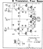
Seems like a pretty simple circuit.
It is an extremely "crude" circuit; typical of the period. It is very short on current gain.
_I_ would consider changing to an opamp and a couple 80+Watt Silicons as you suggest. A bit cleaner (not that it matters). A lot more robust against shorts.
An issue is keeping your polarity-head on straight in this positive ground (negative hot) circuit. I think I got this right.
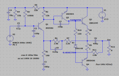
Remove TR1 TR2 R12. Shunt R6 as shown. Jumper in1N4148 diodes (polarity!) near heatsink. Jumper in TL072/TL071s. Shunt R6 as shown to best-center. Idle current is uncertain but probably fine for what it is (not hot, not too raspy). It *may* be down from an optimistic 3 Watts to a solid 2 Watts.
Attachments
Last edited:
Not a bad idea, though the wimpy TL07x seems like a less than ideal choice - would suggest NJM4580 (perhaps RC4580), NE5532 or NJM4556 instead. (Perhaps a type that can swing closer to the rails, too, like OPA(2)132/4.) I think a '4580 with both halves combined via ca. 47 ohms each should have enough grunt. Transistor wise, I'd think something medium power like BD139/140 or MJE340/350 or maybe TIP31/32 should be quite adequate - I mean, we're only talking a 17.5 V single supply and 8 ohm speakers, so that's like what, about 1 A max? Even the original AC187/188 were only rated 1 A, and all of the above are between 1.5 A and 4 A. Going medium power has the advantage of being able to use all-plastic packages that do not require explicit insulation from the heatsink via mica washers or similar.
As mentioned by others, the diodes may appreciate some extra series resistance for some decent bias current (I'd want to have 20-30 mA if the heatsink supports it); I would also add some parallel capacitance to the whole shebang. With some more elaborate biasing, there actually is no real reason to stick with the 1 ohm emitter resistors, and going down to 0.47 ohms may be advisable.
The circuit may appreciate some extra supply bypassing, and having 10-33 pF to go between each opamp output and inverting input may also be beneficial to stability.
If you are going to totally rebuild it, why not just go with a single chip solution, such as an LM1877?
If you are going to totally rebuild it, why not just go with a single chip solution, such as an LM1877?
That'd be worth looking into. I may gravitate toward the simpler solutions, depending on what the customer is willing to spend.
If you are going to totally rebuild it, why not just go with a single chip solution, such as an LM1877?
I'm leaning toward this solution still.
One question: Is there RIAA equalization or anything like that built into this circuit I need to recreate or not remove? (Note it is a ceramic cart)
Really not sure i would qualify changing Ge for Si as being an "upgrade". Certainly not in sound.
One question: Is there RIAA equalization or anything like that built into this circuit I need to recreate or not remove? (Note it is a ceramic cart)
Only the 1Meg input resistance is important.
Really not sure i would qualify changing Ge for Si as being an "upgrade". Certainly not in sound.
Trouble with keeping it Ge is getting the parts. Any suggestions?
One could use the original input transistors to make an emitter follower as a buffer (assuming they are still OK - and even if not, use any other pnp, it really isn't critical). It doesn't have to run at any kind of super crazy current, just enough to drive a typical 20 kOhm input in a competent manner.Only the 1Meg input resistance is important.
This single supply setup is basically begging for a glorified car audio amp... just not sure whether the 2Wpc LM1877 would be cutting it, this kind of supply should be good for up to 4 W / 8 ohms or so. I wouldn't mind something a little higher-power and more "hi-fi". STA540 (used non-BTL) perhaps? Folks in the chip amp department might have a better idea.
You may also want to emulate the original amp's output impedance, which may well be decidedly nonzero, as minimal as the original circuit is - the original speakers may end up sounding a bit thin otherwise. Really nothing unusual for something this old. Try feeding a sine back into the output of the still-working amp via a resistor of something like a few dozen ohms and take note of amplitude as measured by a TrueRMS multimeter on both ends at various frequencies. With some luck a plain series resistor may do the trick well enough. Basically, a version of the Bob Carver challenge.
- Home
- Amplifiers
- Solid State
- Electrohome 860: Upgrade outputs to Silicon from Ge?