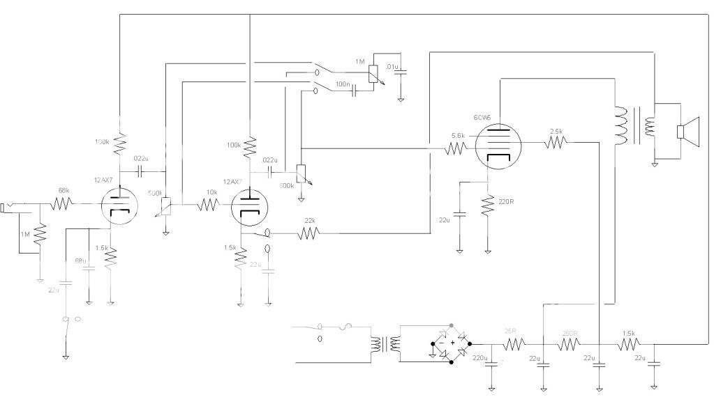
If you move the Tone Stack and dc couple the third to PI, you will have to re-bias the third stage as the anode of the driver tube should be around 65-75V to properly bias the PI. Biasesd as is if stage 3 is driving the PI, the PI will be close to if not in saturation.
Gimp... Yes...I calculated the output of the third stage counting with the loss in tone stack.
I will build this soon... Let´s see what happens..If anyone has any more tips, please leave them here ...
Thanks...
I will build this soon... Let´s see what happens..If anyone has any more tips, please leave them here ...
Thanks...
SemperFi... I thought about putting the tone stack as you said, but as the output in Vpp will be low there, with the intention of saturating the 2nd triode, I was afraid of decrease the gain too much, and don´t have enough to excite the third triode.
I will test another values for the coupling caps... Thanks for the tip.
About the 6BQ7A, as i said, i took the values from the "1975 RCA RC-30 Receiving Tube Manual" (table address bellow). Of course, i will try other values too, especially in the second triode.
But do you think the schema is good enough to not explode??? 🙂
Thanks.
http://www.diyaudio.com/forums/atta...19500381-el86-6cw5-6bq7a-amp-design-6bq7a.gif
If you do not mind putting in a switch you could have both.
Printer2... I can´t see any improvement in the scheme by changing the tone of the place ... Is there any?
i would like your opinion on my last schematic of EL86 + 6BQ7. Could you take a quick look and give your opinion?
Sorry, but this thread has gone farther along than I would have taken it. When I get an idea, I try not to think about it too much, or I will wind up thinking of 1000 ways to make it better and never building anything. So if this were my project, I would be soldering right now! I don't see anything that would prevent the circuit from working.
There is a discussion about where to put the tone control, and the merits of each place. In my amp I tried the tone stack in between each stage and it wound up right where you have it before the PI. I use an LTP for the PI, but your design is just as valid, try it.
I am getting over 300 volts from my power supply, so I would use 350 volt caps and be prepared to deal with more B+ if you get it. The 6CW5's have no problem with 300+ volts on the plate but the screen voltage might be a problem, you might need a bigger zener.
There is only one way to figure all of this out. Build it, test it, tweak it until you get what you want.
I usually build amps bit by bit. Make the power supply, test it. You will get too much B+, ignore it for now just make sure that you get B+ and all the tubes light up. Then build the output stage and test it with a dummy load and a signal generator. Don't have a sig gen? Use a CD player and a test disk or a computer sound card and a test tone wav file. Then add the PI and work your way toward the input verifying that each stage adds more gain.
Tubelab... Thanks a lot... I will start ASAP.
But I must confess that my choice in Phase Invert Cathodyne was because I could not find any examples of 6BQ7A or 6N1P (very similar) setting in LTP. As i STILL do not know how to calculate the resistor values for an LTP, I used Cathodyne Phase Inverter.
But I must confess that my choice in Phase Invert Cathodyne was because I could not find any examples of 6BQ7A or 6N1P (very similar) setting in LTP. As i STILL do not know how to calculate the resistor values for an LTP, I used Cathodyne Phase Inverter.
I have not tried it yet but you should be able to get a different sound by filtering befor and or after you distort the signal. As tubelab said, 'When I get an idea, I try not to think about it too much, or I will wind up thinking of 1000 ways to make it better and never building anything.', that is one idea that I had but never tried yet. While I have breadboarded a number of ideas I have spent too much time doing 'what if's' and I have 18 separate circuits (along with some deviations) that came about from the $100 Buck thread. And that is without getting fancy with different tubes.Printer2... I can´t see any improvement in the scheme by changing the tone of the place ... Is there any?
Build it and tweek it when it is running. You will learn a lot and have a better idea what you want when you are done. A little more than a year ago I more or less did not know a tube circuit from a light bulb. I have come a ways and still have a lot more to learn. You are not going to get it all in one step. So far you are doing good.
I more or less did not know a tube circuit from a light bulb.
You mean to say that there is a difference......I thought these things were light bulbs.
Attachments

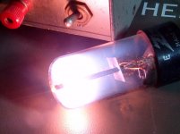
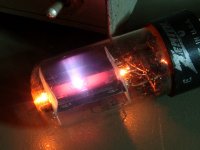
Yeah, I hear you light them up pretty good.You mean to say that there is a difference......I thought these things were light bulbs.
Last question before start... i hope...
Third triode will give an output of 44Vpp (approximately)... After i have a simple tone stack (a little decrease on signal)... And then the PI. I have enough to put the EL86 at maximum level?
Changing the resistors i can go up to 62Vpp on third triode, if necessary...
And tubelab... i hope my tubes don´t go so far... 🙂
Tubelab! You rock! If I ever had a dream lab to work in it'd had to be yours and you'd be my boss. I bet you'd even let me have Friday-beer for lunch🙂
Anyways, I agree some of these threads can go on and on, and suddenly months have passed and nothing been built. But as for me I'm at work and this is a great 'get-away'...although I love my work so it's not that, but we all need breaks, at least I do. Besides, this being a diy discussion in theory there's no end...
Now build this thing b/c I need to know how those 6BQ7s work for you, I have a bunch of them myself🙂
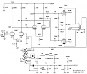
First try on layout... some mistakes??? A little confused, i know...
It is too late here... 5AM... Tired... i go to sleep.
If someone finds something wrong on layout please let me know.
Thanks.
It is too late here... 5AM... Tired... i go to sleep.
If someone finds something wrong on layout please let me know.
Thanks.
Attachments
Last edited:
build this thing b/c I need to know how those 6BQ7s work for you, I have a bunch of them myself🙂
6BQ7s work just great for me. I used 'em to make a cascode LTP, and the sonics are excellent, and there is more than enough extra gain to eliminate a second gain stage.
The main thing about this type is that it was never intended for audio applications, and it does have a funky plate characteristic (undocumented variable-u feature?). You need to get that Vpk up to avoid distortion, but with a good loadline, the distortion is quite low. That, in turn, assumes you have an adequate DC rail voltage.
The other thing to watch out for are the types with the series heaters. These are nastily microphonic and ring like bells. The parallel heater versions don't seem to have this problem.
Attachments
Great to hear that Miles.
They do have a rather funky graph, at least looking at the last page where the Gm, rp, and mu is plotted, the values vary widely from low to high plate current. To me they look like they have a slight remote cut-off characteristic.
They do have a rather funky graph, at least looking at the last page where the Gm, rp, and mu is plotted, the values vary widely from low to high plate current. To me they look like they have a slight remote cut-off characteristic.
Great to hear that Miles.
They do have a rather funky graph, at least looking at the last page where the Gm, rp, and mu is plotted, the values vary widely from low to high plate current. To me they look like they have a slight remote cut-off characteristic.
Given that the 6BQ7 was intended for use as an "up-front" RF preamp good to 300MHz, it's highly likely. Most TV sets apply AGC to both the VHF mixer and the preamp. (They shouldn't -- it's a bad design practice, but they do it anyway.) Variable-u behavior seems very likely.
As for sonic performance, I can definitely vouch for cascode LTP performance. George has used the 6BQ7 as a conventional LTP with similar excellent results. As a regular, grounded cathode, audio voltage amp, I dunnow. For that, it it looks like there are better types: the 6SN7-oids, 6SL7, 12AX7 if proper care is taken with the design (get that plate load up: the 12AX7 has rp= 90K, and it's all too easy to load the plate too heavily for decent sonics). For gains in 6BQ7 territory, 6AU6s as pseudotriodes.
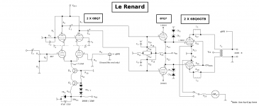
By the way, 25W with a couple of EL86... The designer was not really pessimistic!
Even 45 watts are possible! German musical instruments manufacturer HOHNER once produced the Orgaphon 45 amplifier, featuring two PL84's as finals. Here's the schematics of the power stage:
http://www.hohner.eu/ablage/med_00006406_1264085480_Orgaphon_45_MH_Schaltplaene.pdf
Best regards!
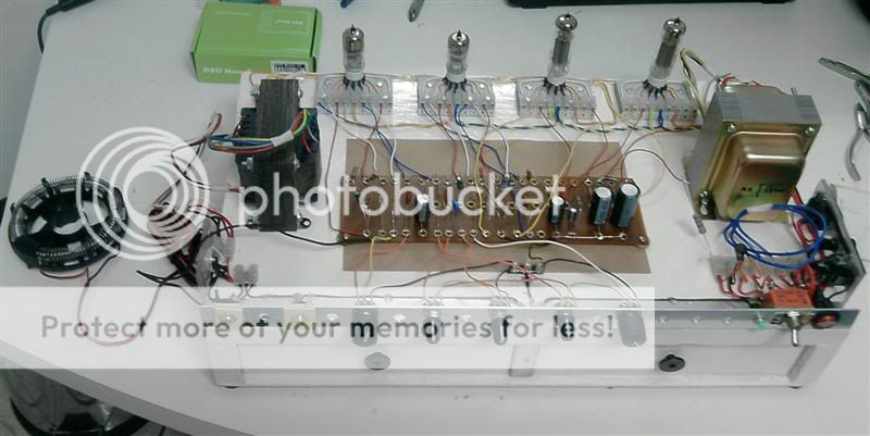
The amp is working... and sounds good.
I changed the inverter ( to a LT inverter), but the rest remains basically the same.
The only problem is a pronounced hum at high volumes.
I am using 2 XL86 (8CW5) + 2 4BQ7A (with heaters in serie), with, of course, a heater supply of 8V (AC).
Probably the 4BQ7A with the heaters in serie are causing the hum?!?
Thanks.
Ps. I am using a lab that I made to test the amp. I know that i have too many wire on the lab, and this increases the hum, but i think the wires are not the only ones to blame. I think the 4BQ7A with heaters in series are the real culprits of the hum.
Last edited:
- Status
- Not open for further replies.
- Home
- Live Sound
- Instruments and Amps
- EL86 / 6CW5 + 6BQ7A amp design