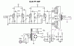
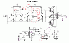
I read in many places that an EL86 can fit on amp designed for EL84, with small adjustments. I took the 18W and i´m trying to adapt to EL86...Well, that's not how you design a good amp. Either you design it properly around the tubes you have, or you copy a good one if you can find one. If you can't do either, you're likely to end up unhappy.
If you have a better solution, please let me know. I'll be grateful. I have a lot of 6BQ7A and EL86 and i want to use them.
davorin, here in my country i can only find 47 or 51V zener, and 1 or 5W only. I think 51V 5W is the better choice, right? It is very cheap.
Mine are RCA, but they have exactly the same size of a EL84. Is it good
They should be fine.
tubelab.com... do you have the link for for the schematic of this "18 watt Lite" with 6BQ7's and 6CW5's? And do you think that my schematic can work?
Any time you use tubes that haven't been tried before you must be prepared to experiment. This often means finding a place to start and then tweaking until you get what you want. Your schematic has the obvious mistake that was pointed out where you need a cap between the plate and the master gain pot. Otherwise it is a good place to start.
I started with some ideas lifted from the 18 watt. com site, added a whole bunch of my own ideas, and laid out a PC board for an amp that fit the $100 parts budget. The schematic of what I started with is in post #794 of the hundred buck amp thread. The design has changed a lot since that post and will continue to change. I will post the design as it exists at the deadline date for the contest (Oct.31). The 6BQ7's were removed early on once I decided to go with the series heater string. There is no series string equivalent to the 6BQ7 so I tweaked the design for the 26AQ8 and the 45B5.
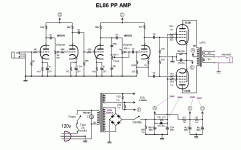
tubelab... I posted another schematic on page 2 of this thread... http://www.diyaudio.com/forums/atta...62-el86-6cw5-6bq7a-amp-design-pp-el86-sch.gif
I already correct this mistake, and others. Can you take a look to see if you can find other mistakes? And if the schematic have a chance of work?
Davorin gave an idea of using zener diode (I'm thinking of using 51V 5W zener) to provide 200V (B+ - 51V) to screen. It will work? I think it is a very good idea...
I will use heater in serie too. I have 8CW5 and 4BQ7A... i will put the 4BQ7A heaters in serie to use only 8V.
Thanks.
And what about it? 2 x 100V 5W zeners to give 200V to screens?!?
Attachments
Last edited:
Coupling cap is still needed after volume control - phase inverter grid sits at 60V or so. Resistors for gain stages are for 12AX7 - 6BQ7 needs more current. Maybe 30K/1W for plate, 510 ohms cathode for 4 mA (-2V bias). 15K resistors and 510 cathode for phase inverter.
You only have 10 mA current for the screens - dropping resistor should be more like 1.5K, 5W, giving 30 mA. (data sheet says peak screen curent is 23 mA per pair) 4x 51V 5W zeners will handle the power better - keep them well separated to dissipate the heat.
You only have 10 mA current for the screens - dropping resistor should be more like 1.5K, 5W, giving 30 mA. (data sheet says peak screen curent is 23 mA per pair) 4x 51V 5W zeners will handle the power better - keep them well separated to dissipate the heat.
A member from a Brasilian forum gave me a good and elegant idea. Put a resistor for grid2 to supply the "Zero-signal screen current - 4mA" = 12K and put in parallel with this 12K resistor a 51V 5W zener, to supply the rest. I think it will work. Any restrictions on that?
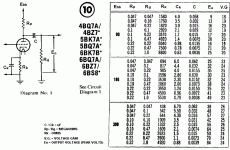
Tom... As i STILL 🙂 don´t know how to calculate the value of the resistors, i took the values from the "1975 RCA RC-30 Receiving Tube Manual". On "Resistance-Coupled Amplifiers" chapter, there is a table with values for the 6BQ7A (attached). I followed the table and tried to use first triode with 24 gain + Eo 70, second with 25 gain + Eo 45 (to saturate easier - if not, i will drecrease 1K2 resistor) and third triode with 25 gain + Eo 60 - all approximate values.As i understood, the way you said me, i will have more gain, but less output voltage. That is right?
And about the inverter... It has a unitary gain, don´t? Will make difference 15 or 30K to anode (and 510 ohms for cathode)? It is not a rhetoric question - i really don´t know... 😉
And about the cap after volume pot, do you think it is necessary cap + grid stopper?
Thanks for your help...
Attachments
Last edited:
Yes, a series Zener will work and saves a few watts of power - it will "sag" with B+, but that may be a good effect for guitar. I didn't have a resistance-coupled table for the 6BQ7 - but those values will work fine. For the phase inverter, use use half the value of plate resistor in cathode, half in plate. Voltage output is likewise half, you need peak-to-peak output of twice the EL86 bias voltage. Phase inverter DOES need cap, doesn't need a grid stopper. 100K grid stoppers are rather large - they'll give quite a bit of high-frequency rolloff - maybe not so bad for guitar.
Now you have... 😉 But take a look at "1975 RCA RC-30 Receiving Tube Manual". There is a resistance-coupled table for 48 different tubes... Including 12A*7, 6AU6, 6AV6, etc... It is very interesting... I didn't have a resistance-coupled table for the 6BQ7 - but those values will work fine...
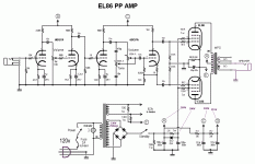
New schematic... What do you think?
Thanks.
Ps. There's a way to delete the schematics on previous posts?
Attachments
The 100k grid stopper is a good idea since the amp will spend a lot of time in overload (hopefully ) and the grid stopper will reduce blocking distortion. The 100k value is not large as the phase inverter has no gain and has a high input impedance. You do not get the rolloff as in a regular gain stage.Yes, a series Zener will work and saves a few watts of power - it will "sag" with B+, but that may be a good effect for guitar. I didn't have a resistance-coupled table for the 6BQ7 - but those values will work fine. For the phase inverter, use use half the value of plate resistor in cathode, half in plate. Voltage output is likewise half, you need peak-to-peak output of twice the EL86 bias voltage. Phase inverter DOES need cap, doesn't need a grid stopper. 100K grid stoppers are rather large - they'll give quite a bit of high-frequency rolloff - maybe not so bad for guitar.
Grid Stopper Resistor Calculator
Now you have... 😉 But take a look at "1975 RCA RC-30 Receiving Tube Manual". There is a resistance-coupled table for 48 different tubes... Including 12A*7, 6AU6, 6AV6, etc... It is very interesting.
New schematic... What do you think?
Thanks.
Ps. There's a way to delete the schematics on previous posts?
Don't worry about the previous schematics. Actually they are good for someone trying to follow the information in the posts.
I have a question for those with more knowledge than I. The stage befor the tone controls has a capacitor on the output to block the dc from getting into the volume pot. Now since this capacitor is in series with the ones in the tone control does it change the shelving frequency (my mind is blank right now, can't think of the term I want)? Since they are in series should one be made larger? Or has that already been taken into consideration?
Printer2... I will test different values of grid stoppers after second and third gain stages... I will start with 100K on all.
And the rest? Is good?
Thanks.
I did not see your last post...
But good question about the cap... maybe it will be better if i put the 10n cap after the 470p cap... The 470p will block DC to tone pot anyway...
New schematic (with grid stoppers + 10n after tone cap) is ready... but i will wait for more tips to see if there something more to change before post it.
Last edited:
Printer2... I will test different values of grid stoppers after second and third gain stages... I will start with 100K on all.
And the rest? Is good?
Thanks.
I did not see your last post...
But good question about the cap... maybe it will be better if i put the 10n cap after the 470p cap... The 470p will block DC to tone pot anyway...
New schematic (with grid stoppers + 10n after tone cap) is ready... but i will wait for more tips to see if there something more to change before post it.
I should have thought of that, with the capacitor. So used to seeing how Fender has done it though, using a larger blocking capacitor. I think your idea might be better. I still would not mind hearing from other more knowledgeable people though.
I am not familiar with your preamp tubes but that aside I do not see anything wrong. If you do not mind my asking, what do you use to draw your schematics?
Actually the input and third stage could use a bigger grid stopper.
Last edited:
... If you do not mind my asking, what do you use to draw your schematics?...
It's embarrassing... i use.... Paint Shop Pro V9... An (very) old graphics editing program...
Sorry, If I would have known that I would not have asked.It's embarrassing... i use.... Paint Shop Pro V9... An (very) old graphics editing program...
Printer2... Don´t worry... i am just kidding...Sorry, If I would have known that I would not have asked.
I need to start using a serious software, like kicad...
But i'm very accustomed with PSP....
Well, I think it may sound a little dark for guitar. I'd reduce the coupling caps to 2-5nF. While on coupling...how'bout placing the tone stack before V3, and direct couple the PI? Kinda like on this schem.
Also 100uF in the supply is a bit big for guitar, unless you want it real stiff, it's more common to use as low as possible capacitance, like 10-33uF for the first cap.
Also 100uF in the supply is a bit big for guitar, unless you want it real stiff, it's more common to use as low as possible capacitance, like 10-33uF for the first cap.
Attachments
Of...forgot...I still think the 6BQ7 should be run a little hotter and not like 12AX7s. I'd start of with Rplate around 24-33kohms and Rcathode 330-680ohms. But it may be that your values give better tone, and it certainly doesnt hurt to experiment, so you could always start off with your values and later simply parallel resistors in there if you want to try other values.
SemperFi... I thought about putting the tone stack as you said, but as the output in Vpp will be low there, with the intention of saturating the 2nd triode, I was afraid of decrease the gain too much, and don´t have enough to excite the third triode.
I will test another values for the coupling caps... Thanks for the tip.
About the 6BQ7A, as i said, i took the values from the "1975 RCA RC-30 Receiving Tube Manual" (table address bellow). Of course, i will try other values too, especially in the second triode.
But do you think the schema is good enough to not explode??? 🙂
Thanks.
http://www.diyaudio.com/forums/atta...19500381-el86-6cw5-6bq7a-amp-design-6bq7a.gif
- Status
- Not open for further replies.
- Home
- Live Sound
- Instruments and Amps
- EL86 / 6CW5 + 6BQ7A amp design
