I would like to place everything into the original box if possible. Will see what I can achieve with shielding.
I was confused with the heater elevation, I thought that its related to the actual tubes, now I see that only the DC voltage matters, thanks for clearing that up.
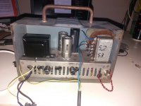
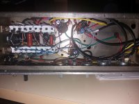
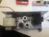
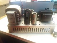
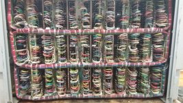
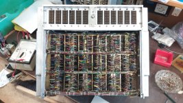
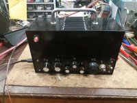
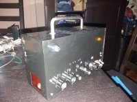
Here are some pictures as promised, you can see the general layout and the restrictions of the box. The underside will be tidied up after finishing the project. Today I wired in the tone section and the second preamp tube, tomorrow I will test it out, its too late now sadly.
I was confused with the heater elevation, I thought that its related to the actual tubes, now I see that only the DC voltage matters, thanks for clearing that up.
Here are some pictures as promised, you can see the general layout and the restrictions of the box. The underside will be tidied up after finishing the project. Today I wired in the tone section and the second preamp tube, tomorrow I will test it out, its too late now sadly.
Attachments
-
 20200528_202513.jpg345.3 KB · Views: 93
 -
 20200603_224812.jpg468.5 KB · Views: 87
 -
 20200603_224743.jpg255.9 KB · Views: 86
 -
 20200603_224720.jpg277.5 KB · Views: 84
 -
 20200603_224616.jpg306.8 KB · Views: 91
 -
 20200603_150033.jpg331.7 KB · Views: 100
 -
 20200602_164007.jpg353.4 KB · Views: 94
 -
 20200602_163957.jpg418.9 KB · Views: 93
Attachments

Last edited:
Wow, that is small! You were not kidding! It must have been quite a challenge to build in such a small space.I would like to place everything into the original box if possible.
-Gnobuddy
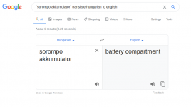
A battery compartment, apparently...What is/was a "sorompoakkumulator"??
-Gnobuddy
Attachments
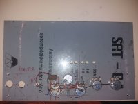
I have changed the faceplate, the "new" one is from an automatic 24V 4A lead-acid battery charger, which is used in railroad crossings here.
I could not figure out what could have been in the box originally, the chassis is coppered-zinced iron, good quality, the box itself is a nicely made one from iron sheets, spot welded together, with original "gills" on the top.
Im used to working with the soldering iron in tight places near wires (see the attached pictures 😀), so not a huge headache for me, but yeah, not the most comfortable piece.
Edit: Altough the HT lines does not carry high currents, but using twisted wires like at the heaters can not hurt, right?
Attachments
Last edited:
So I have finished and double checked the additional wiring and elements, fired up the beast and it works!
But now it squeals like a pig which is getting killed 😀
I can make it oscillate with really low output levels, low gain settings (even before it starts overdriving the gain stages), the squeal is influenced by the guitar tone controls. But can be easily reproduced without anything plugged into the input.
How should I approach this? My first idea is to wire up a dummy load instead of a speaker (to avoid getting deaf) and check each stages output after the coupling capacitor with an oscilloscope, to determine which stage is oscillating.
But what can I do when I found the troublemaker?
Also I have power line hum in my output (not too much, but enough to make me think) which is present with all controls turned to minimum (gains, master volume). When im increasing any controls it stays the same (a little increase when volume is over 50-60%), they add a different tone hum. I feel like it is hum coupled from my power trafo or power cord, right into the OPT, but its not there when no HT is present in the tubes (in standby mode). What could it be?
The idea behind the twisting is to cancel AC magnetic fields in the outgoing and return wires. Most of the power supply wiring will carry DC, and twisting those DC-carrying wires shouldn't make much difference (but it won't hurt).Although the HT lines does not carry high currents, but using twisted wires like at the heaters can not hurt, right?
There are parts of the power supply carrying AC, of course, from incoming AC power socket to transformer primary, and twisting could help a little there. On the secondary side, you have large peak currents and a spiky current waveform through the rectifier diodes (much worse with solid-state diodes), and the usual advice is to keep the area of that loop (TX secondary -> diode -> filter cap -> return to TX secondary) small. I'm not sure if twisting those wires will help much, but I've never tried it.
Congratulations! 🙂...it works!...
Sorry to hear about the squealing. It's a hazard of having lots of gain in a small space, and tubes have big metal electrodes inside, acting as antennae to pick up stray electrostatic fields from other stages and cause unwanted feedback. Add in the high input impedance of tubes, and it seems they are much more susceptible to squealing than similar solid-state circuits.
Definitely get that dummy load in place of the speaker to save your ears (and your sanity)! (Or wire something like 0.1 ohms in series with the 8-ohm dummy load, then wire a speaker across the 0.1 ohms. You can still hear any squealing for diagnostic purposes, but much quieter - I estimate about 70 dB plus or minus 5 dB, which may be tolerable.)
Is there a grid-stopper at the input of the amplifier, between guitar jack and the very first tube? If not, there should be one. It forms a low-pass filter with the input capacitance of the first tube, and basically lowers the voltage gain of the entire amplifier at high frequencies. I'm not sure if it will help with the squealing, but it might, and it's easy to do.
The other thing to consider is inserting interstage attenuators - i.e., fixed voltage dividers, to throw away some voltage gain in between tube gain stages. This might help you to lower the overall gain sufficiently to stop the squealing.
In a modern solid-state amplifier, adding a gain stage and then attenuating the signal to throw away the gain makes zero sense, because both are linear operations, and cancel each other out. But in a tube guitar amp, the additional (and desired) distortion products remain in the signal after we attenuate it back down, so adding more tube stages, and cutting the gain back down in between them, is not a bad thing - it adds "tubey" distortion while keeping the voltage gain from becoming excessive.
-Gnobuddy
Will try the twisting on all AC lines, thanks!
I feel like now its time to finish the box first and then do a final rebuild/tidying up, before any further investigation on a birdsnest build 🙂
I have added a 68k grid stopper right away, as I read on maybe Paul Rubys page. The design also has interstage attenuators originally.
I feel like now its time to finish the box first and then do a final rebuild/tidying up, before any further investigation on a birdsnest build 🙂
I have added a 68k grid stopper right away, as I read on maybe Paul Rubys page. The design also has interstage attenuators originally.
Attachments
A battery compartment, apparently...
If you follow my link, it is clearly a MAK SAT-?? Automatic Battery Charger. The page does not show the SAT-04 model, but the -10 -15 -20 models are the same type of panel with same logo and same number of lamps.
I did miss the fact that this is not the box/chassis' original panel, but some handy scrap flipped and re-drilled.
You dug deeper, and learned more than I did. 🙂If you follow my link...
-Gnobuddy
I have managed to hunt down the main cause of oscillation, my input was way too close to the speaker output. Now it seems fine with a generator on the input. Altought it still starts to oscillate @4-5kHz, when nothing plugged in to the input and the controls are cranked.
A have made some nice pictures along the way, when measuring the frequency response, but either the scope killed the usb drive, or I used a faulty one, anyhow it gave up on me when I wanted to go through the pictures 😡
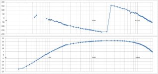
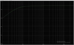
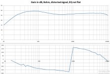
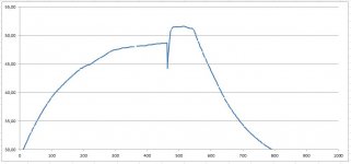
I will attach the results I got. The method used: I gave it about the same amplitude which I get from the guitar (about 300mV) on 1kHz frequency. Then fiddled with the gain stages and output volume, to get out the largest undistorted signal on the output. (Using my eyes and the FFT function)
Then sweeped the range by hand, taking measurements.
Tone stage was set to the values I got by looking at its response with the tone stack calculator.
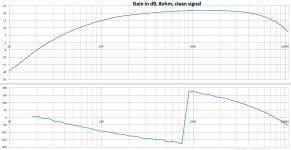
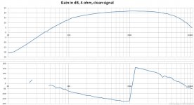
These are results with a 4 ohm load on the 4 ohm tap, I want to repeat it with 8 ohms on the 8 ohm tap, hopefully I could post those scope pictures later with the results.
Edit: Gain is in decibels on the graph.
A have made some nice pictures along the way, when measuring the frequency response, but either the scope killed the usb drive, or I used a faulty one, anyhow it gave up on me when I wanted to go through the pictures 😡
I will attach the results I got. The method used: I gave it about the same amplitude which I get from the guitar (about 300mV) on 1kHz frequency. Then fiddled with the gain stages and output volume, to get out the largest undistorted signal on the output. (Using my eyes and the FFT function)
Then sweeped the range by hand, taking measurements.
Tone stage was set to the values I got by looking at its response with the tone stack calculator.
These are results with a 4 ohm load on the 4 ohm tap, I want to repeat it with 8 ohms on the 8 ohm tap, hopefully I could post those scope pictures later with the results.
Edit: Gain is in decibels on the graph.
Attachments
What is the safe operating temperature range for transformers?
My power trafo is a bit warmer than what I feel comfortable with (I can touch and hold my fingers on the winding insulation and the iron, but its not pleasant, will make measurements). I have spent a few hours while taking the measurements in the undistorted territory and the amp can take a lot more abuse into distortion and a hell lot more to hard clipping, so it can only get worse.
I was thinking about incorporating a bimetal temperature switch somehow fastened onto the transformer to prevent overheating. I have seen trafos with built in thermal switches, so seems right to me. Any opinions on the idea?
If you can, use an input jack that has switch contacts built in, and wire them so that the input is shorted to ground when nothing is plugged in. This should prevent annoying noise pick-up and oscillations due to unwanted stray feedback through the air....t still starts to oscillate @4-5kHz, when nothing plugged in to the input...
Sorry to hear about the unreliable USB drive!Then fiddled with the gain stages and output volume, to get out the largest undistorted signal on the output.
If you can get hold of your guitarist friend, you might ask him/her to offer their opinion. Maximum clean headroom may or may not be the best choice, depending on what the guitarist prefers.
May I ask what equipment you used to measure the complex transfer function?
Your input signal is at about -10 dBV, output at +20 dBV. Was there really only about 30 dB of gain through the whole amplifier?...Gain is in decibels on the graph.
-Gnobuddy
Maybe not all that much worse - this is nominally a class A output stage. True class A draws exactly the same amount of power from the power supply at all drive levels - this is one reason why it is incredibly inefficient!...the amp can take a lot more abuse into distortion and a hell lot more to hard clipping, so it can only get worse...
Of course once you push the output stage into clipping, it is no longer pure class A, and it will draw more power than it does at idle. (But the effect won't be as dramatic as it is with a push-pull class B or AB output stage.)
Is there anything you can do to draw a little less power from the power transformer? Perhaps a slightly colder bias for the EL84? Or supply valve heater power from a small DC switch-mode power supply (instead of from the PT), if you have room to cram one in the box?
-Gnobuddy
I have chosen the simplest solution to try on the oscillation, replaced the preamp tubes (the pentode has been replaced by a 6p14p long ago), but no luck.
I had a better look on the schematic regarding the input switch and spotted an error made by me. I had the 1M resistor on the switched ground, not on the signal line, corrected this also. Now the switch completely grounds the signal line when nothing is plugged in, still no luck.
I have got a suggestion to put a 10-20pF capacitance between the grid and anode of the first tube, no luck either...
The schematic shows shielded wire between the interstage attenuators and the stages, so I put them on their respective potmeters. Do I have to mount them onto the next stages tube socket to make them act like also a grid stopper or it does not matter?
Also checked the temperature of the trafo by wedging a temperature sensor between the iron core and the coils. I have the conclusion that inside the coils could be nearly 60°C or more. (data plot attached)
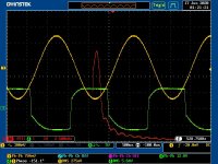
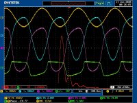
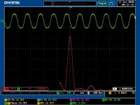
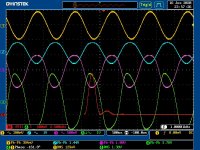
I have taken the measurements with a GWInstek GDS-2104A scope and my phone as signal source. On the scope pictures CH1 - yellow is the input, CH2 - blue is the input of the second gain stage, CH3 - magenta is the input of the third gain stage (+cf+tone section), CH4 - green is the output on the dummy load, RED is the output of the FFT function on the output signal.
An animated GIF image of distorted output signal and its FFT
I had a better look on the schematic regarding the input switch and spotted an error made by me. I had the 1M resistor on the switched ground, not on the signal line, corrected this also. Now the switch completely grounds the signal line when nothing is plugged in, still no luck.
I have got a suggestion to put a 10-20pF capacitance between the grid and anode of the first tube, no luck either...
The schematic shows shielded wire between the interstage attenuators and the stages, so I put them on their respective potmeters. Do I have to mount them onto the next stages tube socket to make them act like also a grid stopper or it does not matter?
Also checked the temperature of the trafo by wedging a temperature sensor between the iron core and the coils. I have the conclusion that inside the coils could be nearly 60°C or more. (data plot attached)
I have taken the measurements with a GWInstek GDS-2104A scope and my phone as signal source. On the scope pictures CH1 - yellow is the input, CH2 - blue is the input of the second gain stage, CH3 - magenta is the input of the third gain stage (+cf+tone section), CH4 - green is the output on the dummy load, RED is the output of the FFT function on the output signal.
An animated GIF image of distorted output signal and its FFT
Attachments
-
 DS0028.jpg86.3 KB · Views: 89
 -
 DS0024.jpg106.8 KB · Views: 88
 -
 DS0014.jpg78 KB · Views: 79
 -
 DS0013.jpg79.7 KB · Views: 82
 -
 DS0007.jpg106.7 KB · Views: 82
 -
 DS0004.jpg112.8 KB · Views: 85
 -
 gain_8ohm_distorted.jpg79.8 KB · Views: 86
 -
 gain_8ohm_clean.jpg96.1 KB · Views: 117
 -
 gain_4ohm_clean.jpg95.3 KB · Views: 122
 -
 trafotemp.jpg27.5 KB · Views: 117
To make sure I understand you correctly: the guitar input jack is wired so that the input to the first triode is shorted to ground when nothing is plugged into the jack? And with the input shorted to ground, you still have oscillation?Now the switch completely grounds the signal line when nothing is plugged in, still no luck.
If that is correct, the next thing I would look at is power supply decoupling. Perhaps the (accidental, unwanted) feedback signal is leaking back through the B+ rails. For example, you could try inserting a resistor in the B+ rail between V4A and V4B, and adding one more filter cap to ground at the top of R23, so that V4B has its own isolated B+ rail, no longer shared with V4A.
You can do the same between V3A and V3B as well.
A small cap like that rolls of the high frequency response, and may be a good way to stop oscillations at, say, 100 kHz. But you reported oscillations at much lower frequencies (a few kHz). That sort of low-frequency oscillation is probably not going to be cured by adding extra Miller capacitance.I have got a suggestion to put a 10-20pF capacitance between the grid and anode of the first tube, no luck either...
I'm not sure I understand you. Shielded wire reduces stray RF and electrostatic noise pick-up, while grid stoppers attenuate high-frequency open-loop voltage gain. They perform very different functions....shielded wire...Do I have to mount them onto the next stages tube socket to make them act like also a grid stopper or it does not matter?
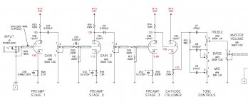
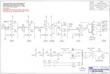
In the last schematic you posted (in post # 48 ), there isn't even a single grid stopper resistor. There should be four...one for every triode.
Are you doing these entirely by hand? Set the phone to a frequency, measure the amplitude and phase-shift with the 'scope, write it down, repeat? Or is your 'scope actually able to control your phone and change its frequency as needed?I have taken the measurements with a GWInstek GDS-2104A scope and my phone as signal source.
I've done it this way in the past, but it is so tedious and takes so much time. I looked for an automated way to do it, either commercial or DIY. In the end I bought an affordable USB scope ( CircuitGear Mini – Syscomp Electronic Design ) that can do complex transfer function measurements.
Unfortunately, the founder of that company passed away, and I think the company is virtually shut down now, as they don't seem to sell anything any longer, though the website is still up.
-Gnobuddy
Yes, you are correct, the input of the amp is shorted to ground when nothing is plugged in. Yet I get oscillation.
I have found good literature here and there, gone through a few books in the last days, mostly from tubebooks.org, so did a few modifications in the supply chain, because that is my next suspect too.
When I started building I did not had the right value capacitors, so everything was undersized. Now I have 120uF @C1, 33uF @C2, 22uF @C3, 33uF @C4, I have also did some more tidy up of the cables inside, changed the HT wiring of the first stage to shielded cable. Also put copperbraiding onto the OPT primary cables, because they are running along the middle of the chassis, between the tube sockets.
Still no changes in the oscillation. I will try to measure the power section and add some more filter stages (will be tricky to fit it inside 🙂 ) as suggested.
I will post the schematic again, it does not use gridstoppers originally, not even on the first tube. I have added 68k onto the first stage as Paul Ruby mentioned it.
I have built the interstage attenuators onto the nearest potmeters, all I wanted to know if that could be my problem. (The schematic shows shielded wiring between them and the stages, so I assumed they were somewhere else originally planned).
I did the measurements by hand right as you stated. Set frequency, write measurement into a spreadsheet, repeat... The scope could handle a 2 channel generator, but I do not have the extension card for it. Luckily it shows anything I want from peak to peak voltage, RMS, phase shift, I just have to read the values from the screen. I think it could be connected to the PC, but I have not looked into it yet, maybe when I get fed up with the manual method.
EDIT: Can you provide some information on the DC filament system you mentioned before? In the PP amp I want tro try DC heating with a ramp up or current limit if possible.
Attachments
Last edited:
Sorry to hear you're having such persistent oscillation. I hope you find a fix soon! This sort of problem can be very frustrating.
It seems Fender Corp. was satisfied with marginal stability, as long as they could save the cost of a few resistors. You can see Leo Fender's penny-pinching accountant philosophy at work in the company, long after Leo himself is gone!
In his book on valve guitar preamps, Merlin Blencowe (aka "The Valve Wizard") recommends using a grid stopper on every gain stage, including cathode follower stages. I've always followed this advice.
Most of the "classic" Fender amps actually had 34k resistance here - they had two input jacks, for high and low input sensitivity, and a network of resistors (including two 68k ones) to provide 6 dB attenuation at the "low" jack. The net effect was to have 34k source impedance to the first triode valve, not 68k.
I should point out that the 250k or 500k volume pot inside the guitar can cause up to 125k source impedance if set to 6 dB attentuation (electrical mid-position), and that can make even more thermal noise than the 68k input grid stopper. So it isn't critical to reduce the 68k. But if hiss from the amplifier is enough to bother you, it's one place where you can make a slight improvement.
To make these sorts of measurements, many people now use their computer's sound-card, along with some measurement software. You are limited to less than 20 kHz bandwidth, but that is hardly a problem for a guitar amplifier. (I never liked this approach because I'm scared of frying my computer if the wrong voltage gets into it, and also because I don't want to use Windows - I use Linux, and couldn't find any suitable software for this purpose).
An interesting DIY solution is described here (amplitude only, no phase): Automating the Measurement of Frequency Response
The hardware is pretty simple, but you still need to write software to control the hardware - to set the oscillator frequency, measure the output voltage, and so on. The author chose not to give any details of his own software, leaving it up to the reader to create their own. I think it might be simpler to use an Arduino rather than a Raspberry Pi, but I haven't actually tried it.
For example, one of the power supplies I've used for this is an 8.4 volt Sony power supply I found at a local thrift-store. I've added a series resistor to drop the voltage to 6.3 volts DC at the heaters.
The only other point I would add is to make sure you ground-reference the DC from the power supply. Most of these little SMPS have the DC output floating, and many seem to use a pair of equal-value, small capacitors wired across the AC mains to let the output "float" to half the incoming AC mains voltage.
In the USA, that means the DC output is actually DC plus 60 volts RMS of 60 Hz AC, at a high source impedance. It is safe to touch because of the high source impedance due to the two small capacitors, but we don't want our valve heaters to have 60 volts RMS AC on them! So I ground either end of the DC heater power supply to the guitar amplifier's power ground.
I've had the same thought as you, to have the heater power come up slowly in a controlled ramp. Most probably there is an internal DC reference voltage used by the switching electronics, and putting a big fat capacitor across that might be all that's necessary to create a slow turn-on. But these power supplies are now so small I think it might not be easy to do mods like this, so I never bothered.
Of course you could add an external MOSFET and some circuitry to turn that on slowly, perhaps using an ancient 555 timer IC to generate PWM to drive the MOSFET gate and ramp up heater current over a period of a few seconds. I never bothered to do that, either.
-Gnobuddy
Old Fender guitar amps did not use grid stoppers either (except at the input), but all three of the Fender amps I've used were only just barely stable - all three would burst into radio frequency oscillation with the slightest change (for example, removing the rear panel on a Blues Junior, or slightly moving the wires running from the PCB to the output valves)....it does not use gridstoppers originally, not even on the first tube...
It seems Fender Corp. was satisfied with marginal stability, as long as they could save the cost of a few resistors. You can see Leo Fender's penny-pinching accountant philosophy at work in the company, long after Leo himself is gone!
In his book on valve guitar preamps, Merlin Blencowe (aka "The Valve Wizard") recommends using a grid stopper on every gain stage, including cathode follower stages. I've always followed this advice.
That will work. But the thermal noise from that single 68k resistor might be the dominant source of noise in the entire amplifier. These days it seems more common to see a 10k resistor there, instead of 68k. Just big enough to stop RF pickup, just small enough not to be the major source of noise in the amplifier.I have added 68k onto the first stage as Paul Ruby mentioned it.
Most of the "classic" Fender amps actually had 34k resistance here - they had two input jacks, for high and low input sensitivity, and a network of resistors (including two 68k ones) to provide 6 dB attenuation at the "low" jack. The net effect was to have 34k source impedance to the first triode valve, not 68k.
I should point out that the 250k or 500k volume pot inside the guitar can cause up to 125k source impedance if set to 6 dB attentuation (electrical mid-position), and that can make even more thermal noise than the 68k input grid stopper. So it isn't critical to reduce the 68k. But if hiss from the amplifier is enough to bother you, it's one place where you can make a slight improvement.
The advice I've always read is that the grid stopper should be as close to the valve socket as possible. Since the purpose is to stop high-frequency RF instability, you don't even want an inch of wire in between the resistor and grid.I have built the interstage attenuators onto the nearest potmeters, all I wanted to know if that could be my problem. (The schematic shows shielded wiring between them and the stages, so I assumed they were somewhere else originally planned).
You are definitely a more patient man than I am! 🙂I did the measurements by hand right as you stated. Set frequency, write measurement into a spreadsheet, repeat...
To make these sorts of measurements, many people now use their computer's sound-card, along with some measurement software. You are limited to less than 20 kHz bandwidth, but that is hardly a problem for a guitar amplifier. (I never liked this approach because I'm scared of frying my computer if the wrong voltage gets into it, and also because I don't want to use Windows - I use Linux, and couldn't find any suitable software for this purpose).
An interesting DIY solution is described here (amplitude only, no phase): Automating the Measurement of Frequency Response
The hardware is pretty simple, but you still need to write software to control the hardware - to set the oscillator frequency, measure the output voltage, and so on. The author chose not to give any details of his own software, leaving it up to the reader to create their own. I think it might be simpler to use an Arduino rather than a Raspberry Pi, but I haven't actually tried it.
I didn't do anything clever at all - I just looked in my junk-box, found a DC switching power supply that could handle the necessary heater current and provide the necessary 6.3 volts, and hooked it up....Can you provide some information on the DC filament system you mentioned before?
For example, one of the power supplies I've used for this is an 8.4 volt Sony power supply I found at a local thrift-store. I've added a series resistor to drop the voltage to 6.3 volts DC at the heaters.
The only other point I would add is to make sure you ground-reference the DC from the power supply. Most of these little SMPS have the DC output floating, and many seem to use a pair of equal-value, small capacitors wired across the AC mains to let the output "float" to half the incoming AC mains voltage.
In the USA, that means the DC output is actually DC plus 60 volts RMS of 60 Hz AC, at a high source impedance. It is safe to touch because of the high source impedance due to the two small capacitors, but we don't want our valve heaters to have 60 volts RMS AC on them! So I ground either end of the DC heater power supply to the guitar amplifier's power ground.
I've had the same thought as you, to have the heater power come up slowly in a controlled ramp. Most probably there is an internal DC reference voltage used by the switching electronics, and putting a big fat capacitor across that might be all that's necessary to create a slow turn-on. But these power supplies are now so small I think it might not be easy to do mods like this, so I never bothered.
Of course you could add an external MOSFET and some circuitry to turn that on slowly, perhaps using an ancient 555 timer IC to generate PWM to drive the MOSFET gate and ramp up heater current over a period of a few seconds. I never bothered to do that, either.
-Gnobuddy
I should thank everybody for all the help and information. The project is now finished, adding some more gridstoppers onto the ECCs and tidying up of the wiring have eliminated my oscillation and hum problems.
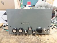
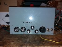
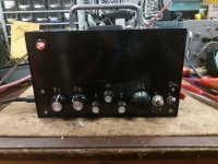
The box is now finished, as can be seen on the pictures.
I have been to the guitar store with the "lunchbox", it got a lot of praises on its sound and quietness, so it turned out very well, I am happy with it.
The box is now finished, as can be seen on the pictures.
I have been to the guitar store with the "lunchbox", it got a lot of praises on its sound and quietness, so it turned out very well, I am happy with it.
Attachments

Congratulations!hordri said:...it turned out very well, I am happy with it.
-Gnobuddy
- Home
- Live Sound
- Instruments and Amps
- EL84 SE mixing mystery box