My OPT supposedly arrived (still have to lay my hands on it), so I took a look on the suggested AX84 schematics. They look great, full of information, targeted to be used by newbies, exactly what I needed. However the forum looks like a ghost town sadly.
I set my mind on reusing the original chassis, it has space already for 2x ECC83 and an EL84 (or soviet equivalents).
Will work my way up block by block, the goal is to eventually reach a HI-OCTANE with some mods. (rythm/lead switch to eliminate the extra gain stage, maybe switch between the original selenium and new Si rectification)
Where should I start bringing it alive? Front end or the power out section?
After building and testing the power supply I can throw all together and simply exclude the unwanted tubes while bringing up the different sections, right?
EDIT: What type of capacitors should I use near the tubes? Im guessing foilfilm where possible, especially in the audio signal route. The schema does not mention the particular types.
Last edited:
You (and I) discovered AX84 well after its prime. It was started in 1998, when the World Wide Web was still mostly empty, and there were still many active USENET groups: AX84.com - The Cooperative Tube Guitar Amp Project...AX84.... ghost town...
Back then, twenty-two years ago, it was much harder to find information on building guitar amplifiers. Tubes had been essentially extinct for thirty years, long enough for a generation or two to grow up with no knowledge of tubes at all. Those few who knew how to build a tube guitar amp, usually were in business, either for big musical instrument companies, or for themselves, so they were not keen on educating the general public about their trade secrets. There were no books I could find on the subject. (Lots of books on electronics and audio, but guitar amps are very different from conventional audio amplifiers.)
So I think that when Chris Hurley started AX84, he was doing something pretty remarkable for the time - using the power of the 'Web to collaborate and create and educate, across many countries.
Sadly, times have changed, the electric guitar is less popular than ever, and the majority of young people of college-going age (the age group that usually has energy and creativity to contribute to such projects) are now more interested in Twitter and TikTok than electronics and engineering. A couple of years ago, Mr. Hurley was talking about shutting down AX84 altogether. I think it was taken over by some other people who did not want to see it die, and they have kept it going as a labour of love. Though, as you say, it is a ghost town these days.
Selenium is quite toxic (particularly if overheated), so please be careful handling them....the original selenium...
You could do it either way. My personal preference is to build the power supply first, then the power amp section, and then work backwards towards the input, one stage at a time.Where should I start bringing it alive? Front end or the power out section?
There are a couple of reasons why I do it this way. One is that the current draw of the power amp section makes the power supply voltages fall, bringing them closer to their eventual final voltages.
Another is more subjective - if I build the power amp first, I can immediately start playing guitar through it! (Using an external preamp, or some guitar effects pedals as a "preamp".)
Being able to play through the amp keeps me motivated to complete the project, and I can hear the effect of each new stage as I build and test it.
Film capacitors are nice, but expensive....type of capacitors...
I often use ceramic capacitors (yes, in the signal path). There are many claims that ceramic capacitors are evil and will ruin your amp and steal your dog, but if you look for carefully conducted measurements of distortion created by ceramic caps in an audio signal path, you will have a hard time finding anything significant. One fellow proudly claims he measured 0.0002% or something like that - this is so low that it's quite ridiculous.
I think the very worst case measurement I could find (a low-voltage ceramic cap with a large signal swing applied to it) produced something like 0.1% THD. In a tube guitar amp, people have a hard time hearing 5% THD. 15% THD still produces a "clean tone". So one-tenth of one percent is utterly negligible.
Modern MLCC (multi layer ceramic chip) caps are particularly nice. They are small, inexpensive, and you can get values up to 22uF, so they make nice stable, long-lived, reliable cathode bypass caps. They are usually rated for low voltages, so not suitable for anode coupling caps and so on.
Here are a few of this type of capacitor at Digikey - as mentioned, I like these for cathode bypass caps - Capacitors | Ceramic Capacitors | DigiKey
-Gnobuddy
Last edited:
Yeah, I have seen that its an archived paged. I love discovering useful archived things from the childhood of the web.
I have piles of old, new, used and NOS parts which I have been collecting and saving up for "this will be good someday/its rarely used but rare and valuable". This is (and many other 0 cost projects) are a good excuse to go over them. I will go the film everywhere way if I can find the parts or I could bum them from work.
Im not a guitar player myself, but wanted to get myself involved in the tube amp topic out of curiosity. Also this little amp will be a good confidence boost for me before building the PP amp for my friend.
Currently im going over this little howto:Paul Ruby First powerup Interesting thoughts are involved there too.
Paul Ruby is one of the names I found on the 'Web a lot when I first began hunting for information about tube guitar amps. I remember seeing his name in connection with DIY "18 watt" Marshal copies, too....this little howto: Paul Ruby First powerup
I know you are an EE, and that means you'll probably find these tube amp circuits extremely simple, like 1960's discrete transistor circuits. But high-voltage safety is another thing altogether, so please be careful - you may have to un-learn some solid-state habits in order to stay safe.
For example, as I'm sure you know, using a wrist-strap to ground your body, and working on a grounded, conductive surface, are good practice when working on static-sensitive solid state devices. But these same practices are extremely dangerous, even lethal, when working on a live tube circuit that might have 400 volts or more inside. The last thing you want is for your body to be grounded - you are much safer sitting on an insulator, like a bird perched on a high-tension power line.
Most of my life, I've worked on low-voltage solid-state circuits, so I've developed plenty of habits I had to unlearn when working on tube guitar amps. I wish I had an actual electricians certification in high-voltage safety - these days electricians are better informed about high voltage safety than most EEs are. (I'm not an EE, to be clear, but have taken a lot of the same college courses that EEs take.)
When I started to work on tube circuits some seven or eight years ago, a lot of the tube safety information I found online seemed to date from 1930 or so. Tips like "Keep one hand in your pocket at all times" seem terrifyingly inadequate. After a century of humans working with dangerous voltages, surely there's something better than that?
So I did a little online research, to find out what electricians use for personal protection these days. It starts with the obvious - modern protective insulating gloves.
So, when working on any live tube circuitry, I wear electrician's class 00 or class 0 insulating gloves ( Insulated Rubber Gloves, Class 00, 0, 1, 2, 3 & 4 - 500v, 1000v, 7.5kv, 17kv, 26.5kv, 36kv ), and safety goggles to protect my eyes from flying sparks.
It's probably also a good idea to wear an insulating apron that covers the front of your upper body, as well as your lap. I've read a few hair-raising stories of DIY amp builders accidentally pulling live tube amp chassis onto their laps. 😱
And that is another very important safety point - make sure the circuit you're working on is securely fastened to the work-bench!
I apologize if you already knew all this. But the EEs I worked with were much more familiar with PADS (PCB design software) than with high-voltage safety, so I thought it best to mention a few things here.
-Gnobuddy
Safety measures are always welcomed, one never can hear them enough to always keep all of them in mind.
Luckily (atleast for me 🙂 ) Im not that average office lurking, low voltage qualified EE, I have a degree in Industrial process controlling and automation. Also did a lot of electrical installation work. Yet im still afraid of working with live line voltages or higher, that helps thinking always safety first.
Where I currently work, we are working near 500-700Volts 75hz and 200V 400Hz, sounds scary enough to watch out 😀 Especially when you see that they are backed up by closet sized inverters and rooms of lead-acid batteries. Fused for several ampers, its not uncommon to find fried snakes and rats, without a problem.
The old folks working in the same field usually have some stories that make you stay alert. Also they have good safety measures, so I have heard about working with one hand numerous times (never enough, sometimes i still forget it), also dont lean on or kneel on anything metal when working.
My work boots are the isolated style, and we are using rubber mats too.
The rubber gloves are a good idea, will check on them. A have seen some pairs used in my life, but cant image that I can work with them inside a box. Maybe there are smaller types.
The apron is also excellent, but mostly could be eliminated by fixing things on the table. Never thought about it... I have pulled lots of solid state, low voltage things in my lap, so a very real problem here indeed.
No need to apologize, your posts always spark new thoughts in my mind, thanks for them!
Extra question: Resistor wattage is indicated in the parts list, but should I worry about voltage rating? The indicated wattages can be obtained with 350WV here, should I try and aim for 500WV even if I have to use larger parts?
The 1/2W ones are rated for only 250WV.
The 1/2W ones are rated for only 250WV.
Resistor voltage rating...
I figured that they only have to withstand the voltange drop on themselves, highest voltage differential is 120-130Volts indicated on the schematic. So I guess I can get away with even 250WV resistors. Right?
Scary enough indeed! 😱Where I currently work, we are working near 500-700Volts 75hz and 200V 400Hz,
Class 00 are the thinnest ones. I wear them if I have to work on a live circuit. But if the circuit is unplugged, and I've used a DMM to verify there are no dangerous voltages inside, I do work with bare hands....rubber gloves...inside a box...
I forgot to mention another safety tip. I add a high-efficiency LED as a "telltale" in the B+ power supply. This lights up to tell me that dangerous voltages are present - if the LED is lit, stay out of the chassis, and make sure class 00 gloves and eye protection are in place!
These days a high-efficiency LED is usually bright enough with 100uA (0.1 mA) of current draw. So with a B+ in hundreds of volts, you find yourself in the odd position of using several megohm resistors in series with the LED!
And yes, I too have pulled low-voltage projects into my lap by accident!
-Gnobuddy
I just use 1/2 watt resistors everywhere, unless more power dissipation than that is called for.So I guess I can get away with even 250WV resistors. Right?
The amps I've built or worked on usually have some 300 - 350 volts B+, I stay away from the 600-volt monsters. 😱
Post #11 in this thread ( resistor maximum voltage rating ) is very informative. George is also an EE, and he knows what he's talking about!
-Gnobuddy
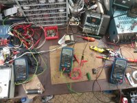
I have a nifty "little" deprez instrument with the right scaling and the resistors needed to scale the measured voltage. Power resistors are on the way and already scavanged a neat a box to build a device to safely discarge the high voltage capacitors. I will post some pictures of the project if you want to see.
I also follow Mr. Carlsons lab, thats where the idea came from in the first place. He also takes safety seriously, thats a main thing I like in his videos.
The post you have suggested about resistors is great. The main thought as I see is the general rule, always oversize sanely, where possible and worth it. I will try and go for 350 and 500 Volts to be on the safe side. My power transformer has an AC 230V secondary (basically thats an 1:1 here), thats under 350V rectified and buffered.
Im not yet all sure that the power transformer will be all up for the show, is it okay to get a suitable load (say 20-40mA for starters) and wire that up to simply see if the trafo heats up after X minutes/hours? Or are there any simple ways to determine max amperage?
That should work....get a suitable load (say 20-40mA for starters) and wire that up...
Maybe a small bulb (the kind used in a nightlight) would make a good load. Here in North America I can still buy 7W, 120V incandescent bulbs, which draw a nominal 58 mA. If they sell 7W bulbs in your country, they should draw 30 mA (at 230 V).
-Gnobuddy
I managed to scavenge fairly proper dummy loads and tested all the secondaries. One by one at first, then gave it a go for about an hour with all loads. The transformer was getting only warm-ish, so thats good news for me.
I have also tested the power section of the amp. I only had 1n4007s at hand, but I do not think that the UF versions would make so much difference.
My unloaded HT is 320V, at full load that drops to 250V, that seems like, this transformer is perfect for the tubes. (full load is tested with 55mA)
The filament secodaries are not seeming so sweet sadly. I have one which gives me 6,6V @300mA and another 6,6V @660mA. I have not found any concrete info on filament voltage vs. lifetime, yet; so I do not know if this should bother me significantly.
My secondary is not center tapped, should I add a hum balance pot right away?
Attachments
It's easy to fix the excessive voltage, just put a small resistor in series with the heater to drop the extra 0.3 volts. For example, 1 ohm in series with a 300 mA heater, to drop 0.3 volts and leave 6.3 volts. Power dissipation is only 0.09 watts in this example, so you can use an ordinary 1/4 watt or 1/2 watt resistor....one which gives me 6,6V @300mA and another 6,6V @660mA.
In practice, measure with your DMM to see what voltage you actually have (it may be more than 6.6V), before you work out what resistance to add to drop it. When you do add the resistor, the heaters will draw a little less current due to the reduced voltage, so now you may find that you need a slightly bigger resistor than you originally thought you did. Usually two steps gets you close enough.
Incidentally, adding series resistance like this (slightly) improves tube life. A cold heater has low resistance, and draws a big spike of inrush current until it warms up. Adding a series resistance (or better, powering each heater from a current source, or a slow turn-on 6.3V volt source) reduces the inrush current, and this should reduce stress on the heater and extend tube life.
-Gnobuddy
I had some questions about grounding, but Paul Rubys page answered all of them for me.
But I see that the filament voltage is elevated in the P1 circuit. Since I have two filament secondaries, do I have to elevate both of them to the cathode of the EL84 or how should I approach this?
But I see that the filament voltage is elevated in the P1 circuit. Since I have two filament secondaries, do I have to elevate both of them to the cathode of the EL84 or how should I approach this?
Attachments
My thought would be to elevate the heater only for the 12AX7, i.e., only the winding you're using to feed the preamp valve.... two filament secondaries...
You may not need any heater elevation at all, if hum is acceptably low without it.
-Gnobuddy
First I have to say thanks again for all your help, guidance and enlivening.
The beast is coming alive, I have thrown together the P1 schematic without the tone section for starters. I have to say that the hum seems to be not a big deal without elevating the heaters for the preamp section (even with my makeshift heater wiring for the tests).
But my power transformer is not a shielded type and its too close to my tubes, I get tons of hum when I put it in its place. Can I simply put an iron sheet onto the chassis between the trafo and the tubes to add some shielding or what material should be used?
On my next move I want to add the tone section and the second gain stage (making it a HI OCTANE). Is it possible to add a DPDT switch to bypass the second tube if needed? Do I need any more components to prevent damaging the second tube, oscillations, etc? (Switch off HT maybe?)
Also if I want to switch between different rectifiers, do I just simply add a DT switch on the HT line before the filtering or should I wait to discharge the caps and then switch on again?
On some schematics I have seen diodes in the HT lines going to the OPT and the second grid of the pentode, are these some kind of extra safety?
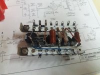
Im also working on the box of the amp, it needs a new faceplate, rust removal, new paint... Will post pictures of the project when it starts to come together.
EDIT: If I want to elevate the heating of the preamp tubes and they are working on the same heater secondary, which one should I tie it to?
The beast is coming alive, I have thrown together the P1 schematic without the tone section for starters. I have to say that the hum seems to be not a big deal without elevating the heaters for the preamp section (even with my makeshift heater wiring for the tests).
But my power transformer is not a shielded type and its too close to my tubes, I get tons of hum when I put it in its place. Can I simply put an iron sheet onto the chassis between the trafo and the tubes to add some shielding or what material should be used?
On my next move I want to add the tone section and the second gain stage (making it a HI OCTANE). Is it possible to add a DPDT switch to bypass the second tube if needed? Do I need any more components to prevent damaging the second tube, oscillations, etc? (Switch off HT maybe?)
Also if I want to switch between different rectifiers, do I just simply add a DT switch on the HT line before the filtering or should I wait to discharge the caps and then switch on again?
On some schematics I have seen diodes in the HT lines going to the OPT and the second grid of the pentode, are these some kind of extra safety?
Im also working on the box of the amp, it needs a new faceplate, rust removal, new paint... Will post pictures of the project when it starts to come together.
EDIT: If I want to elevate the heating of the preamp tubes and they are working on the same heater secondary, which one should I tie it to?
Attachments
Last edited:
You're very welcome! Glad to help....thanks...
If at all possible, first experiment with transformer orientation (rotating it to find a minimum-hum position), and with transformer location (further away from the input.)...hum...an iron sheet onto the chassis...
The next thing to try is an electrically conductive sheet or box around the transformer - not magnetic material, but a good conductor like aluminium. The idea is that the AC magnetic field will induce eddy currents, which by Lenz' law, will create their own magnetic field opposing the original one. If all goes well, the AC magnetic field outside the box will be reduced enough to lower your hum to acceptable levels.
It's also worth trying to shield the input tube itself - there are commercially available metal shields that slip onto matching tube-socket bases to shield the tube, but you can experiment with something simple like aluminium kitchen foil (grounded with a clip-lead) to see if it makes a useful difference, before you spend money on a shielded tube socket.
If those options are impossible, and if the hum is caused by stray magnetic field (and not stray electric field), the "sheet of iron" idea is worth a try. The goal would be to create a low-reluctance magnetic circuit that shunts away leakage magnetic flux from the transformer, and keeps it away from the sensitive parts of your circuit.
There is a special substance called mu-metal ( Mu-metal - Wikipedia ) which is ferromagnetic, and has a very high permeability, and is sometimes used to shield from low-frequency or DC magnetic fields. Unfortunately it is expensive and hard to work with, so it's not something we see often in consumer-grade equipment. (After your make your mu-metal box or shield, it has to be heated in a magnetic field in a hydrogen atmosphere, and cooled slowly to anneal it!)
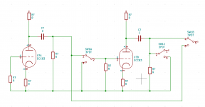
Yes! But there are a few things to consider....Is it possible to add a DPDT switch to bypass the second tube...
For example, in your drawing, the DC voltage on the anode of the input triode is not the same as the DC voltage at the cathode of the cathode-follower. So when you flip the switch, there will be a large step-change in DC voltage (a Heaviside function, which you might remember from when you were studying Laplace transforms at university.) This will make a huge thumping or popping sound every time you switch that extra stage in or out of circuit - definitely not acceptable!
So the first thing to make sure is that there is zero volts DC on all the points you plan to switch - all three terminals of each double-throw switch. You may have to add additional coupling capacitors and resistors to ground as needed to achieve this. If all the terminals are always at zero volts DC, there won't be a loud pop or thump when you switch the extra stage in or out.
For this reason, you also definitely do not want to switch the B+ voltage to any stage on and off - that will cause the loudest possible pops and thumps and bangs of all. A definite no-no!
So far so good. But there is a second problem to consider, and it's something that is peculiar to guitar amp switching. There is no proper engineering term for it, but it is sometimes called "offness". Offness, is, basically, the ratio of signal getting through your closed switch, to signal leaking through your open switch.
Offness would ideally be infinity, but because of stray capacitance in the switch and the wiring, and because of the high input impedance of vacuum tube stages, and because of the high voltage gain in guitar amplifiers, it is quite likely that audible amounts of high frequencies will "leak" through when the switch is off, especially in a high-gain guitar amplifier. This can be very annoying!
One way to improve offness is to put a switch in parallel with a signal, rather than in series with it. For example, if you wire a switch to short a signal point to ground, you can get very good "offness" there.
You can combine the two ideas, using another switch contact that shorts a signal point to ground in the "off" position, but connects it through to the output in the "on" position. The catch is that you now need three or four poles (3PDT or 4PDT) to fully switch an extra gain stage in and out. This usually means you have to use reed relays or something like that in order to get enough poles. Obviously, you switch power to all relay coils simultaneously so they operate in synchronicity.
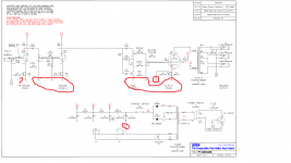
The attached image shows the idea. Input and output of the second gain stage are shorted to ground when that stage is not in the signal path. This means there is less unwanted signal to accidentally leak through to the output. But the price you pay is needing a 3PDT switch rather than a DPDT one.
-Gnobuddy
Attachments
If you're referring to tube rectifiers, sorry, I don't know the answer. I have never used one, and don't plan to ever use one. They don't make any sense to me - silicon diodes are so much better at doing this job, in every way. If you want "sag", just put a resistor in series with a silicon diode....to switch between different rectifiers, do I just simply add a DT switch on the HT line before the filtering or should I wait to discharge the caps and then switch on again?
Can you kindly include a part of a schematic with these diodes, so we know what we're discussing?...diodes in the HT lines going to the OPT and the second grid of the pentode...
I'm not sure I understand the question. If you elevate the heater winding that feeds two tubes, that will automatically raise the heater voltage in both tubes by the same amount, no?EDIT: If I want to elevate the heating of the preamp tubes and they are working on the same heater secondary, which one should I tie it to?
-Gnobuddy
I will post photos later, my phone died out on me.
There are no other options than introducing some kind of shielding between the power transformer and the tubes. The chassis and box is soo tight that only one orientation and placement is possible safely. I will have to scratch my head placing the fuses and indicators.
The tubes are already shielded with their windowed alu caps, thats a feature which came with it.
When I put the trafo down on the table near the chassis (about 10-15cm further from the tubes, somewhat shielded by the side of the chassis), the hum went from irritable and unacceptable level (on room volume) to nearly nothing. Everything cranked, guitar plugged in, I could not believe my ears...
I will try some different materials for the shield, I can try and wrap copper foil onto the insulated windings themselves if nothing seems to work.
Also when I tried moving the trafo I hooked up a larger test speaker, hence the large reduction in hum, there was a distinct 50Hz hum present.
Maybe its time to whip out my rusted scope skills in the shielding process and see whats up, with my eyes.
As for the stage switching, thanks for the in depth description, I felt by gut that I could not get away with those unity step functions. If I add a feature like that I think that should be remote controlled, so relays and whatnot have to be involned. Absolutely no spare space in this box, so I have scrubbed the idea in this build.
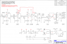
For the diodes in the HT lines, please see this picture:EL84 SE
Thats clear if I elevate a mutual heater secondary, that will be elevated for both tubes. I want to know if there are things to consider about choosing the tube, where I make this connection. Basically does it matter which tubes cathode do I elevate to? The one with the higher voltage? The one further away from the input?
There are no other options than introducing some kind of shielding between the power transformer and the tubes. The chassis and box is soo tight that only one orientation and placement is possible safely. I will have to scratch my head placing the fuses and indicators.
The tubes are already shielded with their windowed alu caps, thats a feature which came with it.
When I put the trafo down on the table near the chassis (about 10-15cm further from the tubes, somewhat shielded by the side of the chassis), the hum went from irritable and unacceptable level (on room volume) to nearly nothing. Everything cranked, guitar plugged in, I could not believe my ears...
I will try some different materials for the shield, I can try and wrap copper foil onto the insulated windings themselves if nothing seems to work.
Also when I tried moving the trafo I hooked up a larger test speaker, hence the large reduction in hum, there was a distinct 50Hz hum present.
Maybe its time to whip out my rusted scope skills in the shielding process and see whats up, with my eyes.
As for the stage switching, thanks for the in depth description, I felt by gut that I could not get away with those unity step functions. If I add a feature like that I think that should be remote controlled, so relays and whatnot have to be involned. Absolutely no spare space in this box, so I have scrubbed the idea in this build.
For the diodes in the HT lines, please see this picture:EL84 SE
Thats clear if I elevate a mutual heater secondary, that will be elevated for both tubes. I want to know if there are things to consider about choosing the tube, where I make this connection. Basically does it matter which tubes cathode do I elevate to? The one with the higher voltage? The one further away from the input?
Distance is definitely your friend here. Monopoles (like mass and electric charge) follow the inverse square law for field vs distance, but power from a magnetic dipole falls away much faster with distance - either inverse square or inverse cube, so that radiated power falls away as inverse fourth power, or inverse sixth power! ( Near and far field - Wikipedia )....When I put the trafo down on the table near the chassis (about 10-15cm further from the tubes...the hum went...to nearly nothing.
So, with a transformer, even a small increase in distance can really reduce hum fields.
Is it an option to mount the transformer off-chassis? Maybe build a separate power supply box, find some suitable connectors, build a plug-in wire harness to connect the PSU to the chassis? If everything is going into a combo guitar amp, you could mount the transformer on the inside of the wooden cab.
I think if you get the copper foil too close to the winding, it will act as a shorted transformer turn, which would be very bad. It would behave like shorting the secondary of your power transformer. 😱I can try and wrap copper foil onto the insulated windings themselves...
It's essential that everything is at zero volts DC, but that doesn't take many additional components (maybe a couple of resistors and caps). The attached image is the simplest switching scheme I can think of - maybe worth a try to see if it works acceptably?...stage switching...
I bought some reed relays for a similar switching project I haven't finished yet. The relays are very small, but they definitely add some complexity, especially because I want to be able to operate them with a foot-switch on the end of a cable plugged into the amp.
Thanks for the schematic!For the diodes in the HT lines, please see this picture:EL84 SE
I cannot make any sense at all of the apparently randomly placed extra diodes. Either I'm overlooking something, or it is another case of Internet nonsense? 😕
The cathode of a 12AX7 is usually within less than 2 volts above ground, so it's pretty useless for elevating the heater of another tube; there's not enough DC voltage there to do anything.Basically does it matter which tubes cathode do I elevate to?
The output tube cathode happens to be a convenient DC voltage that can be used for heater elevation - it's typically ten to twenty volts positive, depending on the output tube you're using. But you can just as well use a voltage divider from B+ to ground, made with two resistors; there is nothing special about using a cathode to provide the elevation voltage.
I use small switch-mode DC power supplies to power heaters with DC, so I have never used heater elevation - there's no need, as there's no AC current through the heater wires to cause hum!
-Gnobuddy
- Home
- Live Sound
- Instruments and Amps
- EL84 SE mixing mystery box