Just curious Paul, why do you think there will be a great improvement by bypassing the 6N1P cathode?
Gain should be enough. I do not have the triode connected input and A-G capacitances but I doubt that the output resistance will be high enough to cause audible roll off due to this.
Is there something else? Normally the local feedback will linearize the stage and you will omit a capacitor of quetionable sonic impact.
This is just a genuine question, no critsism.
/Olof
I have always understood that leaving the cathode un-bypassed causes Ra to vary (owing to local feedback0. I believe that his results in an increase in distortion, something I have always tried to minimise.
In fact, depending on the voltage at the cathode it might well be better to consider LED bias; a normal red LED offers 1.7V with very low effective resistance, making bypassing unnecessary; for around 2.6V one could connect an IR LED in series with a red one.
Paul
PS. 6n1p cathode has only the LED, so it's not bypassed.
It seems there is plenty of gain, using the line out of a portable CD player causes the amp to distort starting at about 60-70% of volume pot position.
What is a good way to scale gain in such an amplifier without degrading the sound?
It seems there is plenty of gain, using the line out of a portable CD player causes the amp to distort starting at about 60-70% of volume pot position.
What is a good way to scale gain in such an amplifier without degrading the sound?
I changed my output tube to 6P15P, as my 3 available 6P14P all give cathode voltages that are at least 1V apart of each other.
The 6P15P's measure a lot more close to each other.
According to my calculation I now have 35mA through output tubes.
But how to calculate the 6n1p bias with a (3mm cheap red) LED in place?
I remember as if I have read somewhere, that LEDs may need at least 5mA through them to be most linear. And even some ideas of directing high voltage to them through a resistor to raise the current. What to think of this?
Here is the amp in its current state
Attachments
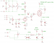
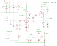
First get rid of R6 4.7k, that should give you a little more current. 6N1P can accept up to 300V on its anodes.
You really need more voltage; was that problem ever solved?
Your distortion may be due to the fact that you are over-driving the stage; what is the output of the CD player?
Paul
You really need more voltage; was that problem ever solved?
Your distortion may be due to the fact that you are over-driving the stage; what is the output of the CD player?
Paul
You voltage drop across R5 / 33k = 3mA.But how to calculate the 6n1p bias with a (3mm cheap red) LED in place?
Hi again!
I still have some tweeking to do on this amp, but when I turn it on I usually end up listening to it for a couple of hours instead of soldering something")
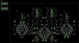
I played a bit with PCB design, see image below.
I have a bit trouble deciding if I want to do a PCB or go point-to-point. P2P is somewhat new to me, and it will leave visible tube socket fastening screws on the top side of the amp. Hotglueing electrolytics may also not be the securest option. On the other hand you can plan the layout as you go and P2P seems to be the preferred tubeamp construction method for most on this forum.
Coming back to PCB option, one problem may be a proper star ground. I could make a double layer board - parts and ground on bottom, tubes and signal on the top (heater voltage would arrive with offboard twisted wire). There would be a separate one sided PCB for the PSU.
What would be your suggestions regarding this?
I still have some tweeking to do on this amp, but when I turn it on I usually end up listening to it for a couple of hours instead of soldering something
I played a bit with PCB design, see image below.
I have a bit trouble deciding if I want to do a PCB or go point-to-point. P2P is somewhat new to me, and it will leave visible tube socket fastening screws on the top side of the amp. Hotglueing electrolytics may also not be the securest option. On the other hand you can plan the layout as you go and P2P seems to be the preferred tubeamp construction method for most on this forum.
Coming back to PCB option, one problem may be a proper star ground. I could make a double layer board - parts and ground on bottom, tubes and signal on the top (heater voltage would arrive with offboard twisted wire). There would be a separate one sided PCB for the PSU.
What would be your suggestions regarding this?
Attachments
I had a thought about the power transformer.
My anode voltages are a bit on the low side. But my power transformer has several taps on the primary winding.
Could it work, when I connect the mains to a let's say 190V tap on the primary (it's 230V tap now)?
Theoretically I shuold get higher voltages on all secondaries. It would be nice to gain 30-40V on anode voltage and 2-3V on filament. This would force me to use DC filament supply, whitch is not a drawback I think.
That should work indeed.Could it work, when I connect the mains to a let's say 190V tap on the primary (it's 230V tap now)?
DC filament on indirectly heated heaters is not a drawback as far as I know.
Hi again!
I still have some tweeking to do on this amp, but when I turn it on I usually end up listening to it for a couple of hours instead of soldering something
I played a bit with PCB design, see image below.
I have a bit trouble deciding if I want to do a PCB or go point-to-point. P2P is somewhat new to me, and it will leave visible tube socket fastening screws on the top side of the amp. Hotglueing electrolytics may also not be the securest option. On the other hand you can plan the layout as you go and P2P seems to be the preferred tubeamp construction method for most on this forum.
Coming back to PCB option, one problem may be a proper star ground. I could make a double layer board - parts and ground on bottom, tubes and signal on the top (heater voltage would arrive with offboard twisted wire). There would be a separate one sided PCB for the PSU.
What would be your suggestions regarding this?
Although you have said you plan to go with point-to-point, might I suggest that your comment of planning layout as you go may not be the best approach. I have had best results when I have made a plan of layout prior to build. I used to do this on paper, but as you appear to know eagle (I did not when starting) I would think the board layout tool would still be a great way to plan layout, even though you are doing p-to-p. You are correct about hot melt glue with capacitors not being acceptable. I see you plan to use a board for the power supply, so that problem is resolved. If you were not using a board you could use a bracket and a zip tie. For the valve sockets, many can be mounted under the top plate, improving he aesthetics. If the top plate is thick enough you can drill a blind hole from underneath and tap a thread with the socket mounted from below and have no visible screw heads. Like http://www.diyaudio.com/forums/tubes-valves/133034-6l6gc-ab2-amp-42.html#post2156897 and http://www.diyaudio.com/forums/tubes-valves/133034-6l6gc-ab2-amp-43.html#post2163817
Good luck with the build.
Chris
Thanks chrish and Bas,
I will defenetly do a wiring plan on paper before assembly. I have some tag strips on the way as well.
The top plate is unfortunately only 1mm thick, so the bottom mounted sockets will still show their screws, I'l try to use good looking screwheads.
I have seen people drilling venting holes around the tube socket, it also seems to divert attention from the screwheads. On the other hand these holes would allow accedental fluid spills or moisture to go straight to the high voltage connections.
Out of my fear for voltage I would prefer to insulate every singele piece of metal that carries voltage/current, but this is not practical I'm afraid.
We'll see how works out
Hi again!
I have finished the amplifier. It sounds great!
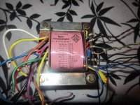
However I have a problem with the power transformer. It will get quite hot in half an hour.
It is a Telefunken tube radio transformer (see picture).
I'm using the 220V tap on the primary,
the 275V, 6,3V 3A, 24V winding on the secondary.
I tried a few things - ran the driver tube on the other 6,3V winding, no change. Then I replaced the 6n1p for a 6n23p, to consume less heater current, still the PT is overheating.
The 24V winding is running my relay delay circuit. I dissconnected it and ran the relay circuit from an external transformer. No difference, PT still overheating.
Since I think I eliminated other options, all thats left is the B+ supply. I'm suspecting it to draw excessive current (also the "choke" is getting warm, but not as hot as the PT). These PT's are generally belived to handle 100-120mA of B+.
Any suggestions on what to do next?
I have finished the amplifier. It sounds great!
However I have a problem with the power transformer. It will get quite hot in half an hour.
It is a Telefunken tube radio transformer (see picture).
I'm using the 220V tap on the primary,
the 275V, 6,3V 3A, 24V winding on the secondary.
I tried a few things - ran the driver tube on the other 6,3V winding, no change. Then I replaced the 6n1p for a 6n23p, to consume less heater current, still the PT is overheating.
The 24V winding is running my relay delay circuit. I dissconnected it and ran the relay circuit from an external transformer. No difference, PT still overheating.
Since I think I eliminated other options, all thats left is the B+ supply. I'm suspecting it to draw excessive current (also the "choke" is getting warm, but not as hot as the PT). These PT's are generally belived to handle 100-120mA of B+.
Any suggestions on what to do next?
Attachments
I'm using the 220V tap on the primary,
the 275V, 6,3V 3A, 24V winding on the secondary.
Hi tuhkam, did you really use the 275Vac tap on the secondary?
Did you measure the B+ at the OT and if so could you confirm that it's about 250 Vdc.
After 30min of operation it is not possible to touch the laminates for longer than a second.
I remember in the testing phase it became only warm and stayed that way for hours.
Back then I did not use the 24V winding of the PT and in the B+ supply the first cap (C2) was unly 47u in stead of 220u that I have now.
In the last weeks I have used 4 Ohm speakers, during testing they were 8 Ohm. The OPT's secondary is 4R.
the first cap (C2) was only 47u in stead of 220u that I have now.
That could be one reason why the trans is getting so hot.
jeff
- Status
- This old topic is closed. If you want to reopen this topic, contact a moderator using the "Report Post" button.
- Home
- Amplifiers
- Tubes / Valves
- EL84 SE advice for a beginner