Just to double check, you did wire the choke between the 220u and the 68u caps right?
This will give you a CLC filter. With 245vAC this should give a idal voltage of 245*sqrt(2)=346V on the first cap. Finite capactance and PT winding resistance will bring this down somewhat. Still if you only have 232 V after the choke and something is drawing a lot of current.
Start by measuring voltage over the cathode resistors in the output stage. They should be 100 ohms per your schematic so each V equals 10mA.
As for the 6N1P's listen to the Gimp I just looked at the datasheet, no direct experience...
/Olof
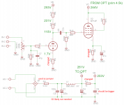
This is the current schematic.
Should I take the high voltage for the output tubes at 220u cap?
Does the "V equals 10mA" also go for the 6N1P? If so, 1.7V suggests a current draw of almost 20mA?
I haven't measued the voltages at EL84 cathodes yet.
The sounds quite good, if compared to it a few days ago. There is a slight high pitched buzz, that gets louder if volume is being turned up and dissapears completely at full volume. It gets also louder if one puts his hand closer to the input wires/pot.
This is most likely normal for a spagetti plate without enclosure.
The heaters are now all on the 3A winding (running 6.22V AC). I did a voltage divider with 2x100 ohm between heater wires and referenced the middle to the ground. Got it a bit more silent with that.
Attachments
When you have solved the mystery of the missing voltage, I have another suggestion. In the power supply you have R2, 1k followed by a small capacitor. I suggest that you replace the 1k with 3 330-ohm resistors and between each add say a 22uF capacitor - i.e. a 22uF after the first resistor and after each of the two others. This will greatly improve the quality of your power supply without costing you any additional voltage.
Also do by-pass the cathode resistor on the 6N1P with a suitable capacitor.
Paul
Also do by-pass the cathode resistor on the 6N1P with a suitable capacitor.
Paul
Last edited:
On 6N1P cathode you have 1.7V drop over 470R = 3.6mA, not 20mA ("V equals 10mA" comment was referring to EL84 with 100R cathode resistor)This is the current schematic.
Does the "V equals 10mA" also go for the 6N1P? If so, 1.7V suggests a current draw of almost 20mA?
Last edited:
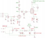
OK, starts to look good. Approx 30mA through the output tubes and 3,5mA through the 6N1P.
I would probably increase to somewhere around 40mA in the output.
Now you can start to fine tune. Or be satisfied...
However as you stated C8 should be bigger, C3 is borderline(-3dB around 20Hz)
/Olof
I would probably increase to somewhere around 40mA in the output.
Now you can start to fine tune. Or be satisfied...
However as you stated C8 should be bigger, C3 is borderline(-3dB around 20Hz)
/Olof
hemgjord thanks,
The amplifier sounds quite good I think.
What would be the reasonable limit for C3? I was thinking on 68u to 100u. Currently C3 is a 400V cap, is this vital?
There is a slight difference in channel levels, this is most likely related to component tolerances or the condition of these second hand parts. C3 are quite old I think, the output tubes may also have worn differently during the last decades.
Anyway, I will tune it a bit more (LED for 6N1P cathode and more current through the output tubes) and buy new electrolytics for all positions.
Would there be a point in adding a decoupling cap to 6N1P anode supply, close to the tube?
I had 33u there, but had to remove them because of the voltage rating of 250V.
C8 should be bigger indeed.
Thanks for help everybody!
C3=100 uF or larger. Voltage rating should be around 35 vdc (gives you a safety margin). Larger voltage rating is fine but not necessary.
Sure a lot of point actually . Put it between r5/6.
Sent from my GT-N7000 using Tapatalk 2
Would there be a point in adding a decoupling cap to 6N1P anode supply
Sure a lot of point actually
. Put it between r5/6.Sent from my GT-N7000 using Tapatalk 2
Last edited:
I'd suggest you also try LEDs on EL84 cathodes. Two parallel strings of 4 LEDs (I had more luck with yellow and orange than red ones for low impedance) would give you some 7-8 V bias and around 40mA current with your voltages (two strings are required to share the current as most cheap LEDs are not 'comfortable' with over 30mA, you can also insert a 1R resistor so that you can measure voltage across it and compute current).What would be the reasonable limit for C3? I was thinking on 68u to 100u.
...
Anyway, I will tune it a bit more (LED for 6N1P cathode and more current through the output tubes) and buy new electrolytics for all positions.
With LEDs in EL84 cathode there is no longer any need for C3.
NOTE that R7 will have to be reduced to 300K or less since LEDs behave like fixed and not cathode bias.
The enhanced mode and more specifically, the simultaneous G1 and G2 (in phase) type of driving, was an issue for me. I did for the first time with transistors, than with transformers and now with tubes. This circuit is running fantastically well. THD is very linear and timbre is amazing rich. Tubes are El84 and ECC82.
By judio at 2012-06-22
Nafty
An externally hosted image should be here but it was not working when we last tested it.
By judio at 2012-06-22
Nafty
tuhkam, what is the software called by the way with which you are making your schematics?
The software I used is a free version of Eagle. I added some voltages etc. with some image editor later.
Thanks.The software I used is a free version of Eagle. I added some voltages etc. with some image editor later.
Looks interesting. But I don't understand what it has to do with this thread? Why don't you start a new thread. I would love to hear your circuit explained.The enhanced mode and more specifically, the simultaneous G1 and G2 (in phase) type of driving, was an issue for me. I did for the first time with transistors, than with transformers and now with tubes. This circuit is running fantastically well. THD is very linear and timbre is amazing rich. Tubes are El84 and ECC82.
Just curious Paul, why do you think there will be a great improvement by bypassing the 6N1P cathode?
Gain should be enough. I do not have the triode connected input and A-G capacitances but I doubt that the output resistance will be high enough to cause audible roll off due to this.
Is there something else? Normally the local feedback will linearize the stage and you will omit a capacitor of quetionable sonic impact.
This is just a genuine question, no critsism.
/Olof
- Status
- This old topic is closed. If you want to reopen this topic, contact a moderator using the "Report Post" button.
- Home
- Amplifiers
- Tubes / Valves
- EL84 SE advice for a beginner