Thanks all for the information and insights.
With the previous tests, the load resistor was connected to the output with a coaxial cable. I replaced it with a resistor that is wired with 2 separate leads and that seems to have improved things as I did not observe the instability with either the 120pF or 270pF compensations caps. Going up to 390pF, the amp went into instability close to its limit at around 8V output.
I now took apart the mockup and awaiting to receive the chassis, once I put it together with proper wiring I'll re-run the tests
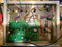
I assembled the amp in the chassis and unfortunately still have instability. I wanted to start a new thread but there is alot of information here already (although it is way far from the original intent of the thread).
Here is some recap of info:
* Output transformers are Hammond 1650FA 7.6K pri, 43% UL
* Cathode bias resistors 270ohm Mills MRA (non inductive wirewound), with 1000uF Nichicon UPW caps
* All other resistors (including stoppers) are metal film.
* gNFB with 270pF compensation cap.
The previous conclusion regarding the coaxial cable was incorrect, the difference I saw was actually due to changing the load resistor.
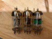
I ran a variety of tests, UL vs Pentode, 3 different 12AT7's, and 2 different load resistors.
Each combination affects instability in some way.
In the table below, "ok" means there wasn't instability and I could reach max power, otherwise the number is the power output when instability starts.
As seen,
- Pentode works better than UL
- one 12AT7 is less affected than the others
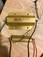
- one load resistor affects instability less then the other
There were a few recommendations earlier but hoping the new information can give more targeted feedback for next steps.
Thanks all
Here is some recap of info:
* Output transformers are Hammond 1650FA 7.6K pri, 43% UL
* Cathode bias resistors 270ohm Mills MRA (non inductive wirewound), with 1000uF Nichicon UPW caps
* All other resistors (including stoppers) are metal film.
* gNFB with 270pF compensation cap.
The previous conclusion regarding the coaxial cable was incorrect, the difference I saw was actually due to changing the load resistor.
I ran a variety of tests, UL vs Pentode, 3 different 12AT7's, and 2 different load resistors.
Each combination affects instability in some way.
In the table below, "ok" means there wasn't instability and I could reach max power, otherwise the number is the power output when instability starts.
Code:
	GE	Brimar	Tele
Pentode	ok/7.5W	ok/6W	ok/ok
UL	ok/4W	8W/1W	ok/5W
As seen,
- Pentode works better than UL
- one 12AT7 is less affected than the others
- one load resistor affects instability less then the other
There were a few recommendations earlier but hoping the new information can give more targeted feedback for next steps.
Thanks all
Attachments
Last edited:
Wiring is critical with the EL84, they were even used in transmitters. I do not know what the schematic looks like but depending on the driver I use a 100 -150Pf capacitor from g1 to ground and depending on OPT quality I use a capacitor between plate and g2 with a resistor in series (if it is UL) or if run as a pentode a capacitor (up to 5nF) and resisitor in series (can be 20K, can be lower but I try to keep it high) parallel to the primary to dampen resonance.
Sometimes a small capacitor across the secondary solves the problem. Since I prefer point to point wiring I will put some ferrite beads on the wires close to the tube socket.
Since it was easy I tried this and unexpectedly it helped...
I put a 100nf C0G cap across the secondary and the instability went away.
I tried the "worst" combination, i.e the Brimar tube with the large output resistor in UL and it was stable....
Can anyone explain what function this cap is doing?
As per my comments in posts #26 and #34, it is likely your answer would be in a gain-phase plot with feedback disconnected - and with and without your 100nF COG. It may well be that the cap reduces the gain sufficiently at higher frequencies such that the stability margins improve once feedback is connected.
Thanks for the reminder trobbins, I'll try that later tonight.
I tried various cap values and found that as little as 2.2nF was sufficient to suppress the instability, whereas around 500pF was not enough.
I've also found that a small cap across the blue / blue-yel in the primary suppressed it while across the brown / brown-yel did not.
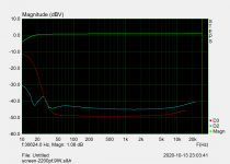
For reference, this is a FR/distortion plot at 90% output with feedback and 2.2nF cap.
I'll disconnect the feedback and run the 2 other plots
I tried various cap values and found that as little as 2.2nF was sufficient to suppress the instability, whereas around 500pF was not enough.
I've also found that a small cap across the blue / blue-yel in the primary suppressed it while across the brown / brown-yel did not.
For reference, this is a FR/distortion plot at 90% output with feedback and 2.2nF cap.
I'll disconnect the feedback and run the 2 other plots