itsik,
Just looked at your picture. What value did you use (how did you determine) the value for the FB cap?
To implement the adjustable bias all you need remove are the four bias resistors then run leads to an off-board biasing network. I found the JJ tubes should have a bit less bias than the Russian-made tubes. I believe the JJs have a lower dissipation rating than the Ruskies.
Also a Hammond 156R choke (~$15) in place of R1 (150 ohm, 5W) killed the last little bit of hum on my build.
S.
Thanks for the feedback Steve. I have actually read through the WOS blog (which I believe was your unit?) Regardless it was super helpful.
For choke, I have a Hammond 193H, 5H 69R on the left side. The 2 resistors in series there were attempts to reduce B+ to around 320V ... I need to finalize that resistor value once I put in a CL90 on the transformer primary.
For feedback caps, this is interesting.
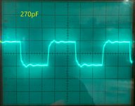
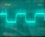
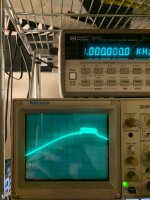
The reason why they are mounted that way is because I was experimenting with values. I went with the method George recommends (10khz square wave), and as I tried the values 120pF, 270pF, 390pF 470pF the square wave looked better as the value increased.
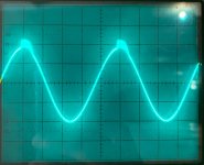
The issue though is that from 270pF and onward, a 1khz sine wave distorts pretty quickly, at around 3W of output.
So right now I have 120pF because it makes the square wave look better than no cap, and I can reach full output without that odd distortion.
I've tried 3 different types of 12AT7 / 6201, and various output tubes and the distortion is the same.
Last pic is of the distortion I mention.
For choke, I have a Hammond 193H, 5H 69R on the left side. The 2 resistors in series there were attempts to reduce B+ to around 320V ... I need to finalize that resistor value once I put in a CL90 on the transformer primary.
For feedback caps, this is interesting.
The reason why they are mounted that way is because I was experimenting with values. I went with the method George recommends (10khz square wave), and as I tried the values 120pF, 270pF, 390pF 470pF the square wave looked better as the value increased.
The issue though is that from 270pF and onward, a 1khz sine wave distorts pretty quickly, at around 3W of output.
So right now I have 120pF because it makes the square wave look better than no cap, and I can reach full output without that odd distortion.
I've tried 3 different types of 12AT7 / 6201, and various output tubes and the distortion is the same.
Last pic is of the distortion I mention.
Attachments

Guilty as charged re: WOS. The prototype for the series was made with old Heathkit iron. It sounded OK but the build for the WOS articles was with new Hammonds, which sounded noticeably better.
With the Heath trannies I used resistors in the primary to drop the filament voltages to nominal or slightly lower values. I also put another RC filter ahead of the main B+ supply to burn off a extra little B+. Mounting the 5AR4 off-board was handy.
With the Hammond power trannie I used the 125 volt primary tap. Filament and B+ voltages came out about right. With the stock EL84 cathode res the current draw was a bit high using JJ tubes. The Hammond build was stock whereas the Heath build has adjustable bias.
See pic of Heath build. The bias pots and meas. points are accessed through a small cover on the top of the chassis.
Cheers, Steve
Attachments
Wiring is critical with the EL84, they were even used in transmitters. I do not know what the schematic looks like but depending on the driver I use a 100 -150Pf capacitor from g1 to ground and depending on OPT quality I use a capacitor between plate and g2 with a resistor in series (if it is UL) or if run as a pentode a capacitor (up to 5nF) and resisitor in series (can be 20K, can be lower but I try to keep it high) parallel to the primary to dampen resonance.
Sometimes a small capacitor across the secondary solves the problem. Since I prefer point to point wiring I will put some ferrite beads on the wires close to the tube socket.
An last resort may be a small choke consisting of ten or so windings over a 47 Ohm 3 Watt carbon resistor in the plate lead close to the socket may be needed.
Using transmitter construction methods stops the trouble.
Quite frankly most of the designs on the internet do not adress instability and it will bite you in the proverbial place with speakers and crossovers with varying capacitance / inductive load.
Regarding NOS 12AT7 - I no longer bother with them after reading a report that stated that out of the 20 NOS tested not one came close to decent specification. The good ones have disappeared.
Antoehr thing to be alert to is that although a tube may be labelled like "12AX7" (ECC 83) the tubes are not the same. They may work in the same circuit but also may not work. Just check the recommended operating points in the manufacturers' datasheet. And that is only to be expected since other manufcaturers did not make these tubes under license. If they were identical then they would have to pay a license fee.
This is why you'll find that a 12AX7 is not the same as an ECC83 with the ECC83 normally having a higher specifications. But then Amperex was bought by Philips and labelled the ECC83 as a 12AX7 for the local market. So it is knowing where your tube originated from.
The Philips EL84 was regarded as one of the best, after all Philips originally designed the tube. Prices are now unaffordable if you still can find a good one. (Be aware of the fakes). I managed to find a stash of Polam / Telam tubes, they were made in Philips subsidary in Poland. Last lot I bought were pricey but still nowhere what a Philips labelled one would have cost (especially a quad). Have not tested them since we are moving, they look NOS but it is always a gamble with so-called NOS tubes (I think as NOS potentially standing for Next Online Scam).
You may even find that a specific 6BQ5 is actually not a pentode but a relabelled 7189 or that it is a beam tetrode. (some manufacturers resorted to doing it if they had plenty of stock of one lot and ran out of stock on the other lot, or they bought up stock from another affiliated manufacturer which may or may not be of similar specification). It happened when I was at Philips. Nuff said.
Last edited:
Thanks for the feedback Steve. I have actually read through the WOS blog (which I believe was your unit?) Regardless it was super helpful.
For choke, I have a Hammond 193H, 5H 69R on the left side. The 2 resistors in series there were attempts to reduce B+ to around 320V ... I need to finalize that resistor value once I put in a CL90 on the transformer primary.
For feedback caps, this is interesting.
The reason why they are mounted that way is because I was experimenting with values. I went with the method George recommends (10khz square wave), and as I tried the values 120pF, 270pF, 390pF 470pF the square wave looked better as the value increased.
The issue though is that from 270pF and onward, a 1khz sine wave distorts pretty quickly, at around 3W of output.
So right now I have 120pF because it makes the square wave look better than no cap, and I can reach full output without that odd distortion.
I've tried 3 different types of 12AT7 / 6201, and various output tubes and the distortion is the same.
Last pic is of the distortion I mention.
The ripple should be less than 5% of the total height of the square wave and the lneght of decay less than 25% of the width at 5Khz to pass in the past.
If there is a leading spike it should not be more than 10%.
Check with a triangular wave too, watch reversal at top bottom and how linear it is at the crossing of the 0 line.
Don't test at full power, use 90%.
Don't sweat it.
PS the top and the bottom of a square wave is actually DC so a perfect square wave represents lots of losses. This is why triangular is more important but in days past a decent triangular wave generator was more expensive and required a larger circuit to make, square wave generation was lots easier which why it came in fashion.
Last edited:
Itsikhefez, your 1kHz sinewave 'distortion' in post #22 looks to me like feedback instability rather than 'distortion', which indicates you may need to check the gain and/or phase margin of your amplifier. The output transformer may be allowing resonances to just broach instability conditions.
If that instability is just from basic responses around the feedback loop, and not any parasitic couplings due to wiring etc, then you may need to noticeably reduce the level of feedback to attain sufficient stability margin, or otherwise dive in to the world of gain/phase measurement and subtle methods of improving stability margins (such as the capacitor value across the feedback resistor).
Your square wave responses in post #22 indicate some ringing at circa 80kHz and another higher frequency above circa 200kHz, although it is a bit difficult to extract as the scope divisions are not aligned with the test frequency.
One possible issue with using a higher square wave test frequency is that it may influence the ringing response seen on the flat waveform portions by having some harmonic energy content that aligns or misses an amplifier ringing frequency.
Are you able to trigger on the 1kHz sinewave 'distortion' and identify the ringing frequency involved?
Thanks for the info trobbins and AmadeusMozart.
Lot's of information to digest... this is my first P-P amp and still getting the hang of things.
Feedback instability makes more sense, I did not know how to characterize what I was seeing.
Wiring is currently a mess because of the mock up, I'll have to retest once everything is in a chassis and tidy. I'll also try running a triangular wave.
Regarding feedback, AFAIK the default BOM has a relatively small amount of feedback. With the 5.1K resistor, there is about 8dB of feedback with an 6.6K:8 OPT, mine is 7.6K:8 so pretty close.
As I mentioned with 120pF across the feedback resistor, the circuit is stable. The next value I have is 270pF which at that point is unstable.
I'm not entirely sure how to recognize the ringing frequency, but can try with some guidance.
I can also run the FFT with ARTA but am probably limited to which frequency I can show because of sound card limitations.
If you are sure your test square wave is 10kHz, then you should be able to use a 20us/div scope timebase to show one period of 10kHz aligning with 5 scope divisions.
Can you trigger the scope with the 1kHz sinewave so that the 'fuzzy' distortion remains within the screen's view as you reduce the timebase down from the 200us/div you used in post #22 to say 50us/div or even 20us/div, as that should then show up a section of high frequency ringing in the sinewave.
Can you trigger the scope with the 1kHz sinewave so that the 'fuzzy' distortion remains within the screen's view as you reduce the timebase down from the 200us/div you used in post #22 to say 50us/div or even 20us/div, as that should then show up a section of high frequency ringing in the sinewave.
Itsikhefez, your 1kHz sinewave 'distortion' in post #22 looks to me like feedback instability rather than 'distortion', which indicates you may need to check the gain and/or phase margin of your amplifier. The output transformer may be allowing resonances to just broach instability conditions.
If that instability is just from basic responses around the feedback loop, and not any parasitic couplings due to wiring etc, then you may need to noticeably reduce the level of feedback to attain sufficient stability margin, or otherwise dive in to the world of gain/phase measurement and subtle methods of improving stability margins (such as the capacitor value across the feedback resistor).
Your square wave responses in post #22 indicate some ringing at circa 80kHz and another higher frequency above circa 200kHz, although it is a bit difficult to extract as the scope divisions are not aligned with the test frequency.
One possible issue with using a higher square wave test frequency is that it may influence the ringing response seen on the flat waveform portions by having some harmonic energy content that aligns or misses an amplifier ringing frequency.
Are you able to trigger on the 1kHz sinewave 'distortion' and identify the ringing frequency involved?
This explains why the initial measurments was different, they were taken
with feedback connected. Later readings taken with feedback disconnected
was more in line with my experience.
Yes, look for instability. Make sure screen and grid stoppers are
carbon-comp as a start.
petertubs I've been curious if I need to replace those grid resistors to carbon comp... unfortunately I didn't find conclusive information in particular regarding 12AT7 and EL84.
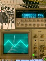
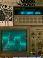
trobbins, I put back the 270pF cap and I _think_ I got the correct samples.
The 10khz square wave is at 20us/div and the 1khz sine wave is 50us/div.
trobbins, I put back the 270pF cap and I _think_ I got the correct samples.
The 10khz square wave is at 20us/div and the 1khz sine wave is 50us/div.
Attachments
What you want for grid/screen stoppers are non-inductive resistors, pure ohm. Noise and
precision is of less or none importance. This is to reduce the Q of the circuit. If nothing else
works try to add ferrite pearls on the plate connections ( on the wire to the transformer)
In the oscilloscop pictures post #30 the third ( the sine) shows a clear oscillation at
the top. This is what you want to get rid of. I suppose you have the amp loaded with
a power resistor, to further provoke it connect a cap of 1uF in parallel. If it is free from
oscillations with the cap you are probably close to target.
Last edited:
Thanks for the help.
I do need one clarification though-
With the 120pF capacitor in the feedback loop there is no oscillation, but the square wave looks bad.
The question is, why not just use 120pF as opposed to trying to solve the oscillation with the higher feedback capacitor?
I do need one clarification though-
With the 120pF capacitor in the feedback loop there is no oscillation, but the square wave looks bad.
The question is, why not just use 120pF as opposed to trying to solve the oscillation with the higher feedback capacitor?
Get some carbon comp resistors first. One thing at a time.Thanks for the help.
I do need one clarification though-
With the 120pF capacitor in the feedback loop there is no oscillation, but the square wave looks bad.
The question is, why not just use 120pF as opposed to trying to solve the oscillation with the higher feedback capacitor?
What is bad with the square wave ? Maybe this is what you should have.
Post #30 sinewave spurious oscillation appears to have a very high frequency.
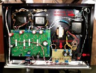
Initially, that may be from parasitic coupling due to poor routing of wires from the pcb terminals to the output transformers (as indicated by photo in post #16) - so I would suggest you twist and keep physically separate the following groups of wiring:
- speaker/test resistor and feedback wiring for each channel
- plate and screen and B+ wiring for each channel
Your pcb has a grid and screen stopper already, so I can't see any point in changing that. Adding an anode stopper at the pcb terminal may be a temporary option for faultfinding, but doesn't seem appropriate at the moment.
If you still get that HF oscillation then perhaps post another photo of your bench setup, including how you are probing with the scope (the scope probe should have the ground clip going to the pcb main ground trace).
After that it may be worthwhile plotting gain and phase of the amplifier with feedback disconnected, to see if there are any unexpected peaks/shift related to the output transformer and your total setup.
This is a popular myth. The tiny inductance of a typical resistor will be totally damped by the resistance. Resonant effects are only significant with very-low ohmage resistors, and even then only in the tens of megahertz. This is a non issue for a valve amp.What you want for grid/screen stoppers are non-inductive resistors, pure ohm.
The SPP board is indeed based on a pretty generic design. I got dozens of requests for something like SY's RLD amp done on a PC board, so I created the SPP. Very few people actually buy it though.
Extensive testing performed during the design revealed that many EL84 / 6BQ5's start to draw grid current while still well into the negative grid voltage region. This can unbalance the phase inverter leading to higher than expected distortion at power levels approaching clipping. This should not be an issue in the low power measurements. It as been over 15 years but I think I saw this only in power levels above 15 watts.
The LED biased SPP was an experiment in quasi fixed bias. I used 4 white SMD camera phone LED's wired in series to develop about 14 volts of cathode bias. They were mounted on a ceramic PCB which was also the heat sink.....and not a good enough heat sink. One of the LED's shorted out while cranking something loud a full volume. I had fetched these LED's out of the trash when I was a phone engineer at Motorola and had no more of them, nor knew their specs. The amp was a bit more dynamic than the typical cathode biased SPP, and could be pushed harder before distorting. At one point I had it cranking out nearly 30 WPC on 430 volts of B+ and 250 volts on G2 using old Sylvania 6BQ5's rescued from a discarded Baldwin organ. The only new production tubes that would take this abuse were JJ's. This was about 15 years ago. I have no idea how their current tubes are in this respect.
I have never been a fan of large doses of GNFB. Some users have cranked the feedback up far more than I do without issues, but this is very OPT dependent.
My amp uses come crummy 6.6K OPT's that were designed for guitar amps. I am using an 820 pF cap in mine to make the square waves look OK. This does not cause any issues.
This is generally true, except when using high Gm tubes that were originally intended for RF applications. The worst offender is the 5842 / WE417A used in my TSE board. That thing will oscillate if given the slightest chance. I have seen them oscillate in a TSE board if a 4.7K metal film grid stopper is used with some sloppy input wiring. In this case a CC resistor with a ferrite bead over each lead was needed to kill the oscillation.
The 12AT7 was originally designed for TV and radio tuner use up to 300 MHz. It can oscillate if given a chance, but it is usually docile. I have never seen a old US production tube oscillate in the SPP, and I have tried lots of them I have several hundred old used military pulls to choose from. Some new production "12AT7" don't resemble a 12AT7 at all internally. I have some older JJ's that look like they borrowed the plate from a 6DJ8 / ECC88.
Extensive testing performed during the design revealed that many EL84 / 6BQ5's start to draw grid current while still well into the negative grid voltage region. This can unbalance the phase inverter leading to higher than expected distortion at power levels approaching clipping. This should not be an issue in the low power measurements. It as been over 15 years but I think I saw this only in power levels above 15 watts.
Was thinking of LED biasing, I know that George tried it with SY's recommendation but I don't know the details.
The LED biased SPP was an experiment in quasi fixed bias. I used 4 white SMD camera phone LED's wired in series to develop about 14 volts of cathode bias. They were mounted on a ceramic PCB which was also the heat sink.....and not a good enough heat sink. One of the LED's shorted out while cranking something loud a full volume. I had fetched these LED's out of the trash when I was a phone engineer at Motorola and had no more of them, nor knew their specs. The amp was a bit more dynamic than the typical cathode biased SPP, and could be pushed harder before distorting. At one point I had it cranking out nearly 30 WPC on 430 volts of B+ and 250 volts on G2 using old Sylvania 6BQ5's rescued from a discarded Baldwin organ. The only new production tubes that would take this abuse were JJ's. This was about 15 years ago. I have no idea how their current tubes are in this respect.
AFAIK the default BOM has a relatively small amount of feedback. With the 5.1K resistor, there is about 8dB of feedback with an 6.6K:8 OPT
I have never been a fan of large doses of GNFB. Some users have cranked the feedback up far more than I do without issues, but this is very OPT dependent.
with 120pF across the feedback resistor, the circuit is stable. The next value I have is 270pF which at that point is unstable.
My amp uses come crummy 6.6K OPT's that were designed for guitar amps. I am using an 820 pF cap in mine to make the square waves look OK. This does not cause any issues.
What you want for grid/screen stoppers are non-inductive resistors, pure ohm.......This is a popular myth. The tiny inductance of a typical resistor will be totally damped by the resistance
This is generally true, except when using high Gm tubes that were originally intended for RF applications. The worst offender is the 5842 / WE417A used in my TSE board. That thing will oscillate if given the slightest chance. I have seen them oscillate in a TSE board if a 4.7K metal film grid stopper is used with some sloppy input wiring. In this case a CC resistor with a ferrite bead over each lead was needed to kill the oscillation.
The 12AT7 was originally designed for TV and radio tuner use up to 300 MHz. It can oscillate if given a chance, but it is usually docile. I have never seen a old US production tube oscillate in the SPP, and I have tried lots of them I have several hundred old used military pulls to choose from. Some new production "12AT7" don't resemble a 12AT7 at all internally. I have some older JJ's that look like they borrowed the plate from a 6DJ8 / ECC88.
I doubt the resistor inductance was the culprit. I suspect the ferrite beads we doing the work.I have seen them oscillate in a TSE board if a 4.7K metal film grid stopper is used with some sloppy input wiring. In this case a CC resistor with a ferrite bead over each lead was needed to kill the oscillation.
As a retired RF engineer from a 41 year career at Motorola I would tend to agree.
As a "I know what works in my board" kind of guy, I know that you need a carbon comp resistor for the grid stopper on the 5842 if it's a Raytheon (the most common) tube. I have not needed, nor do I recommend a ferrite bead, but it does help if the input wiring is sloppy, a twisted pair, or both.
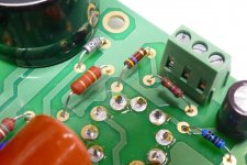
Here are pictures of two boards grabbed at random off my desk. The board with the 4.7K CC is what I recommend for the average builder. The resistor is spaced about 10mm off the board because that's what many builders do. It has been tested with everything from thin RF rated (RG174) coax cable to speaker wire as the wiring to the input jacks, and everything from a cheap phone to a tube line stage attached to it. Twisted pair, grounded at both ends, driven by a low impedance source is worst case. The amp is "sniffed" with a RF spectrum analyzer good to 3 GHz during testing.
The board with the 6.2K CC is what I build for myself. I have a lifetime supply of vintage Allen Bradley 6.2K CC's.
Both are unconditionally stable with everything I tried and several different brands of tubes.
This should not be needed with a 12AT7 unless something in the wiring is resonant at an RF frequency within the range of the 12AT7 (up to 300 MHz). Grounding the shield of the input cable at both ends can do it.
The only other place I have needed to use a CC part is when a mosfet is directly driving the grid of a high Gm TV sweep tube. Since the grid may be driven positive on short music peaks a low value stopper resistor is needed to avoid distortion, often 100 to 470 ohms. Here a CC with two beads is often needed to avoid a high power random frequency radio transmitter.
As a "I know what works in my board" kind of guy, I know that you need a carbon comp resistor for the grid stopper on the 5842 if it's a Raytheon (the most common) tube. I have not needed, nor do I recommend a ferrite bead, but it does help if the input wiring is sloppy, a twisted pair, or both.
Here are pictures of two boards grabbed at random off my desk. The board with the 4.7K CC is what I recommend for the average builder. The resistor is spaced about 10mm off the board because that's what many builders do. It has been tested with everything from thin RF rated (RG174) coax cable to speaker wire as the wiring to the input jacks, and everything from a cheap phone to a tube line stage attached to it. Twisted pair, grounded at both ends, driven by a low impedance source is worst case. The amp is "sniffed" with a RF spectrum analyzer good to 3 GHz during testing.
The board with the 6.2K CC is what I build for myself. I have a lifetime supply of vintage Allen Bradley 6.2K CC's.
Both are unconditionally stable with everything I tried and several different brands of tubes.
This should not be needed with a 12AT7 unless something in the wiring is resonant at an RF frequency within the range of the 12AT7 (up to 300 MHz). Grounding the shield of the input cable at both ends can do it.
The only other place I have needed to use a CC part is when a mosfet is directly driving the grid of a high Gm TV sweep tube. Since the grid may be driven positive on short music peaks a low value stopper resistor is needed to avoid distortion, often 100 to 470 ohms. Here a CC with two beads is often needed to avoid a high power random frequency radio transmitter.
Attachments

The last set of scope pictures clearly show instability.
I glanced over the thread but did not see a remark what output transformer has been used.
The plate and g2 wires of an UL transformer can create instability - I've read schematics where it was specified that the plate and g2 wire had to be shielded.
If an UL connection is being used then I would temporary remove the UL connection, replace by a resistor and test to check if this is the culprit before doing anything else.
AM
The Philips PR01, PR02 and PR03 range of metal film resistors have a datasheet (https://www.vishay.com/docs/28729/pr010203.pdf) that indicates a 100 to 470 ohm value has an impedance that is effectively resistive out to at least 100MHz.
A single small ferrite bead meant for emi suppression (eg. EMI Suppression Beads (2673004801) - Fair Rite) is likely to be mainly resistive and add a rising impedance of up to 10's of ohm impedance out to circa 100MHz.
Given the pcb design, and close location of the grid and screen stoppers, the practical wiring out to a transformer is likely to be the dominant influence for any observed high frequency resonance imho.
- Home
- Amplifiers
- Tubes / Valves
- EL84 measurable distortion between different makes