have monoblocks 4x EL84 in triode - driven by 2x ecc81 -
The EL84 are on 430v and amp gets hot
Have to replace the trafo so have to decide new anode voltage on the EL84 ...
neg grid voltage a.o.
Virtual Valve Museum has a EL84 on max anode 300V and max anode 550V la=0
The anode of the EL84 (7) is with a 91ohm connected to the grid g2
If the new anode voltage is f.e. 330v does the 91ohm be lowered as well...
Not looking for power cause speakers are 94dB .. ...any hints .....
Last edited:
Max, you better look for an established design if you want to build your own amp. Without the necessary knowledge one can't design an amplifier. If you want to experiment and learn while doing so, start simple with an EL84 and ECC81. Read a good book (the ancient stuf is not so practical), Bruce Rosenblit wrote a nice primer. Have fun!
What are the EL84 cathode voltages?
The 91 ohm resistor between g2 and a is a triode strapping resistor. It's value is not critical, unless there is danger of oscillation. You can keep it the same in any case, or increase it to some value, say 470 ohms or 1k.
The 91 ohm resistor between g2 and a is a triode strapping resistor. It's value is not critical, unless there is danger of oscillation. You can keep it the same in any case, or increase it to some value, say 470 ohms or 1k.
Things needed to know before doing anything.
Anode load resistance?
Cathode or fixed bias?
Usually when you decrease voltage you increase current, power supply might not handle extra current.
When you say runs hot please be more specific. Bias? Temp? Transformer?
Anode load resistance?
Cathode or fixed bias?
Usually when you decrease voltage you increase current, power supply might not handle extra current.
When you say runs hot please be more specific. Bias? Temp? Transformer?
Wrong mains voltage?
Is it possibe that the amp was made for North American mains to give some 220-240V on EL84 anode and now that you have it plugged into a European wall socket you get approx. double that?
Is it possibe that the amp was made for North American mains to give some 220-240V on EL84 anode and now that you have it plugged into a European wall socket you get approx. double that?
give it a try anyway..
Anode load resistance 150k ( 75k and 75K 460uF + 460uF in series
Cathode bias -22 v - should be - 24
cannot be more specific cause got the amp ....and discovered was too hot before in my hands
brown spots on trafo and board..it is a 220v design
when on variac decrease voltage sounds much much better .....but extra current comes in sooner or later so replace the trafo seems best options....but need to give the specs for another trafo of course
what about http://www.diyaudio.com/forums/tubes-valves/185823-unexpectedly-good-el84-amp.html
anode on 330v ...
And cathode voltages ....120 mV now variac on 180v) 250-275mV when on 220v (bias pot regulatable)
Last edited:
so try to discover:
when anode voltage is 330 -what could the next parameters be .... neg bias and grid
There must be an excellent combination of these 3 to have the amp produce music to its finest
when anode voltage is 330 -what could the next parameters be .... neg bias and grid
There must be an excellent combination of these 3 to have the amp produce music to its finest
Max, what brand / model are we talking about? a schematic would be nice. Or a picture of the inside. There are many good designs available, take your time to choose one based on what iron you have under the hood.
Beginner`s Guide to Tube Audio Design by Bruce Rozenblit - code 3004 | Hifi Collectivejaap: where to download Bruce Rosenblit...
Anode load resistance 150k ( 75k and 75K 460uF + 460uF in series
I mean the output transformer primary impedance. This is important to know if you are trying to figure out what operating point you want your | | EL84 wired triode. Either way you need to get the anode/screen voltage down.
What's is the cathode resistor values? Are the cathode resistors shared?
If you can draw up a quick schematic it would be advisable or at the very least give us some decent pictures to see what we are dealing with here.
do not want to change but get the anode voltage down from 430 to around 330v
have to adjust the rest....
have to adjust the rest....
do not want to change but get the anode voltage down from 430 to around 330v
We need to know what we are working with before just dumping voltage into heat. This would include all primary and secondary taps on power transformer and the rectifier and filter network. Either trace it out and draw up a schematic or at the very least take a picture most of us can figure it out by that. Without this we are relying on crystal balls.
Once you get your voltage down then you can figure out the best bias condition for you.
do not want to change but get the anode voltage down from 430 to around 330v
How about changing to a choke (or small cap, then choke) input power supply?
I mean the output transformer primary impedance. This is important to know if you are trying to figure out what operating point you want your | | EL84 wired triode. Either way you need to get the anode/screen voltage down.
Thanks yes should be down....output transformer difficult to measure get 0.5 ohm to .....fluke keeps running ...so how to measure accurately../
What's is the cathode resistor values? Are the cathode resistors shared?
Cathode resistors are 10ohm paralled with a 100uf elco
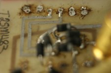
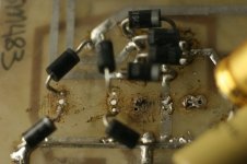
If you can draw up a quick schematic it would be advisable or at the very least give us some decent pictures to see what we are dealing with here
i get the pictures here ...cannot get a schematic yet
You are measuring the DC resistance... you need find out the primary impedance not resistance.output transformer difficult to measure get 0.5 ohm to .....fluke keeps running
We need to know what we are working with before just dumping voltage into heat. This would include all primary and secondary taps on power transformer and the rectifier and filter network. Either trace it out and draw up a schematic or at the very least take a picture most of us can figure it out by that. Without this we are relying on crystal balls.
primary side of trafo from left to right
1:150v
2: 60v <> 5:60v these 2 are connected
3: 13v
4: 13v
6: 65v
secundary side follows (have to be careful ...not my own and been much too hot.... it is a tiny triode 25 old manley cannot find schematics anywhere)
primary side of trafo from left to right
1:150v
2: 60v <> 5:60v these 2 are connected
3: 13v
4: 13v
6: 65v
secundary side follows (have to be careful ...not my own and been much too hot.... it is a tiny triode 25 old manley cannot find schematics anywhere)
Attachments
Last edited:
You are measuring the DC resistance... you need find out the primary impedance not resistance.
okay ....how....?
With the OPT disconnected from the output tubes and the speaker/load, apply a small AC voltage to the secondary winding say 5Vrms and read the voltage at the primary winding, then we can use the ratio of the voltages to calculate the primary impedance for a given load impedance.
secundairy side - left to right
1 and 3 feeding rectifiers anode 430v
(2 non active)
primary 3 and 4 feed rectifiers for neg bias see above
4 travels to pin 4 of all El84 .. heather
and 6 to pin 4 of 1ste ecc81 ..heather
5: earth
1 and 3 feeding rectifiers anode 430v
(2 non active)
primary 3 and 4 feed rectifiers for neg bias see above
4 travels to pin 4 of all El84 .. heather
and 6 to pin 4 of 1ste ecc81 ..heather
5: earth
Attachments
Last edited:
- Status
- Not open for further replies.
- Home
- Amplifiers
- Tubes / Valves
- EL84 in triode