Power supply:
http://www.schematicheaven.com/fenderamps/champ_5f1_schem.pdf
Preamp:
http://www.ax84.com/static/hioctane/AX84_Hi-Octane_080507.pdf
Good luck.
http://www.schematicheaven.com/fenderamps/champ_5f1_schem.pdf
Preamp:
http://www.ax84.com/static/hioctane/AX84_Hi-Octane_080507.pdf
Good luck.
Attachments
Last edited:
Stalker,
Are you going to try and implement the triode/pentode switching, that is, after you've finished enjoying the fruits of your present labor? It shouldn't be that hard really.
When I get around to building my amp after my domestic project is finished I'll definitely be doing that. I've already been kicking around some ideas. Because it won't be a guitar amp it will look completely different from your implentation. I won't need extensive overdrive capability like you do so I'll be using 6sn7's for voltage gain. I also will use grid bias to fix reliability issues I had with the Tigris. That means that along with switching screen wires from OPT to B+ I'll also have to switch bias voltages. It's more complicated but its definitely achievable.
Right now I'm kicking around ideas for switching tube bias without having an intermediate position that leaves the grid open. That can't happen for obvious reasons. I'm inclined to borrow Tubelab's powerdrive circuitry and add 2 parallel identical resistors in the voltage fixing chain. The grid will be attached to the bottom of one of the resistors. A switch will then short short across one or the other one so that the voltage change will appear but will not result in high currents through the tube even during the instanteous switch not-connected position. Also that topology will maintain current at the same level through the fet regardless of position, except when the tube is drawing grid current on peaks. That would happen anyway in all implementations of Tubelab's powerdrive.
Stalker,
I'm inclined to borrow Tubelab's powerdrive circuitry and add 2 parallel identical resistors in the voltage fixing chain. The grid will be attached to the bottom of one of the resistors. A switch will then short short across one or the other one so that the voltage change will appear but will not result in high currents through the tube even during the instanteous switch not-connected position.
Obviously I'll need to similarly add identical resistors downstream in series for each parallel path. Otherwise voltages wouldn't change because the common point would be the same in each parallel path with just one resistor for each path. Same voltage then even with switching. Duh.
Last edited:
Are you going to try and implement the triode/pentode switching, that is, after you've finished enjoying the fruits of your present labor? It shouldn't be that hard really.
It isn't but the schematic is for youngb4's amp, mine has a triode/pentode switch. It's set as 100% triode or 100% pentode, no mixing as I'm a little afraid for the well-being of my NOS tubes.

For a hifi amp there's less risk of destruction so I plan to try that someday.
Your idea of grid bias is fine but there's also the possibility of paralleling cathode's resistors with a switch to get different bias. You won't need to turn off the amp during changes as there will be always one resistor in the tube's cathode. Your approach seems more risky because if something goes wrong...

Post the schematic in this forum before building the amp. If I were you I would ask Tubelab about it, if he says it's OK, the it is OK.
Hey youngb4, forgot to reply to your question. You need a transformer capable of providing at least 100mA.
Well guys,
Here's the schematic I came up with. I'm sure it doesn't look like anything you've ever seen before. It's uses the ideas I've gotten elsewhere but uses my own implementation which is wildly different from what it originated from. I wasn't able to get a good pspice model for the pentode modes so I just used triode modes to put it together and used data on the internet I plugged in for pentode biasing etc.
I know pspice isn't exactly real world and this especially isn't because you really can't model mechanical switches or relays very well. I also didn't want to get bogged down on details that many of you have already figured out like long tail CCS implementation so I just put in a generic constant current source. I think just one stage of voltage amplification will be just sufficient (barely).
The OPT is one I got from Menno that allows 10% cathode feedback so that's why it looks like its mirrored and that the speaker is in a weird place. I also decided in this implementation that since I can optimize it with grid biasing I may as well use resistors to drop the plate voltage in triode mode because triode mode likes lower voltage and more current so it can operate in the linear portion of the transfer characteristic.
There's probably obvious stuff I'm missing. What I'd most like to know is if Tubelab thinks this implementation of changable grid biasing using powerdrive will work. I did my best to put it together so that there is very little change in current through the Fets even with changes in grid drive. The fet I used is just one that was in pspice because I don't have a good model for one I would actually use. I won't be putting it together for quite a while because household projects I've got but I sure would appreciate any input. Thanks in advance.🙂
Eric
Here's the schematic I came up with. I'm sure it doesn't look like anything you've ever seen before.
It's uses the ideas I've gotten elsewhere but uses my own implementation which is wildly different from what it originated from. I wasn't able to get a good pspice model for the pentode modes so I just used triode modes to put it together and used data on the internet I plugged in for pentode biasing etc.I know pspice isn't exactly real world and this especially isn't because you really can't model mechanical switches or relays very well. I also didn't want to get bogged down on details that many of you have already figured out like long tail CCS implementation so I just put in a generic constant current source. I think just one stage of voltage amplification will be just sufficient (barely).
The OPT is one I got from Menno that allows 10% cathode feedback so that's why it looks like its mirrored and that the speaker is in a weird place. I also decided in this implementation that since I can optimize it with grid biasing I may as well use resistors to drop the plate voltage in triode mode because triode mode likes lower voltage and more current so it can operate in the linear portion of the transfer characteristic.
There's probably obvious stuff I'm missing. What I'd most like to know is if Tubelab thinks this implementation of changable grid biasing using powerdrive will work. I did my best to put it together so that there is very little change in current through the Fets even with changes in grid drive. The fet I used is just one that was in pspice because I don't have a good model for one I would actually use. I won't be putting it together for quite a while because household projects I've got but I sure would appreciate any input. Thanks in advance.🙂
Eric
Attachments
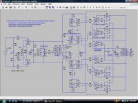
It's a pretty crappy copy of the schematic I printed. For some reason pspice doesn't show my schematic in the library file to send to you. So I had to print screen and sent that. Does anyone here know how to load the schematics directly from pspice. I know there must be a way.
Don't get confused by the missing coupling capacitors between the balancing pot and the 6sn7 load resistors. They were in there originally but got lost when I cut and pasted the version with the switches shown. This version doesn't actually work on pspice because it hates switches so I wasn't able to catch that deletion. There maybe other things that got lost in translation for the upload version also, but hopefully not. Mostly I'm interested in big picture problems others may see and not the fine details - I'm not there yet.
I hate Pspice schematics, hard to read, don't know if it's the poor contrast or what. Anyway, I would open a new thread, this one was mostly about a guitar amp and not many people are going to see the schematic.
I don't like the plate resistors, believe me a 6V6 in triode doesn't need a lower voltage. I have a 6V6 PP triode amp. BTW the 6V6 has a higher bias voltage in triode not lower.
The 6SN7 would be OK but with feedback robbing gain it won't and you'll need feedback when using pentodes. Are you going to use a preamp?
I don't understand mosfets so no comments. Again this is a hifi amp and this is mainly a hifi forum so I think you should start a new thread.
Last edited:
I hate Pspice schematics, hard to read, don't know if it's the poor contrast or what. Anyway, I would open a new thread, this one was mostly about a guitar amp and not many people are going to see the schematic.
I don't like the plate resistors, believe me a 6V6 in triode doesn't need a lower voltage. I have a 6V6 PP triode amp. BTW the 6V6 has a higher bias voltage in triode not lower.
The 6SN7 would be OK but with feedback robbing gain it won't and you'll need feedback when using pentodes. Are you going to use a preamp?
I don't understand mosfets so no comments. Again this is a hifi amp and this is mainly a hifi forum so I think you should start a new thread.
Yes, I agree it needs a new thread. But I don't think I'll start one until I'm closer to actually building it.
As far as your other suggestions I think you may be misunderstanding my out of the box thinking. Triode mode draws more current and that's why my previous amps blew up (several times) even with cathode biasing. It was the 6v6 that did it. But the intent of my circuit is to put the triode mode closer to class A which is really what it is intended for anyway. To do that you have to operate closer to the middle of the transfer curve and less towards the bottom. This circuit allows you to do that with grid biasing. The plate resistor drops it to 250 volts and the grid bias going down allows it to operate in the middle of the transfer characteristic while still allowing the tube to operate within its heat dissipation limits. The plate resistor will drop about 4.5 watts. Not ideal but... I'm not just doing this stuff to be different.
I've actually thought about it.
The cathode feedback in the OPT uses only 10% feedback. It's a much more efficient use of feedback than global feedback and I think even one 6sn7 stage has enough gain for my needs. I've worked it out.😎
LOL, I just don't follow you. With 300 volts at the plate and 35mA of current the 6V6 does just fine. Bias voltage would be -22. With 250 volts at the plate and a bias voltage of -16 it has 35mA of idle current. Is that closer to class A?
Last edited:
Stalker, let's try to keep a civil discussion and accept that humans are not infallable, both you and me. If you would have looked closer than just trying to poke holes in what I'm doing you would seen that generally class A refers to not only no plate current cutoff but also the point on the characteristic curve it operates in. Generally class A operates higher on the curve but I know you understand this. Plus this circuit can be adjustable for the placement on the curve while maintaining it within heat disipation limits by droping the plate voltage in triode mode simultaneously. This isn't rocket surgery. I haven't said your implementation is wrong but please don't be threatened by a new implementation that may also work. An open mind is a wonderful thing, try to cultivate it.🙂
Eric
Eric
Last edited:
You were right, I've just done a sim, less power but closer to class A. In fact full class A.
If you would have looked closer than just trying to poke holes in what I'm doing/QUOTE]
..I was just trying to understand.
An open mind is a wonderful thing, try to cultivate it./QUOTE]
I agree and I keep trying.🙂
Last edited:
Stalker thank you for all your updates and the posted output schematic, I wish I could get to testing sooner so I could share some of my results but it looks like I wont be able to start for another month 🙁 and I'm sure many will lose interest in this topic by then. I'm just curious, would you mind posting a rough sketch of the power supply you used for your specific build (namely the transformer you used and the B+ values) I'm brushing up on some power supply theory so I can truly optimize one for my specific build and just want to do some comparisons 🙂 part of me thinks I shouldn't be so obsessed with the theory and I should just start building, but it's all I can do for now!
Thanks again for your help
Thanks again for your help
sorry stalker, ignore half of my previous post, I overlooked the link in which you posted the champ power supply that you used. 😱 what model of transformer did you use though, and also, did you use a tube rectifier as in the schematic or silicone diodes (which I am planning on using)?
and I'm sure many will lose interest in this topic by then.
We have put them to sleep. 😀
sorry stalker, ignore half of my previous post, I overlooked the link in which you posted the champ power supply that you used. 😱 what model of transformer did you use though, and also, did you use a tube rectifier as in the schematic or silicone diodes (which I am planning on using)?
It doesn't have a name, it comes from an old tape recorder. Secondary voltage: 0 - 230. I'm using silicon diodes, full wave bridge.
PSUD2
haha true, true. I'll just have to wake them with an abundance of rocking once my amp is up and running! 😎
Thank you for the link, I have heard of this software, I just kept forgetting where to find it!
Thank you for the link, I have heard of this software, I just kept forgetting where to find it!
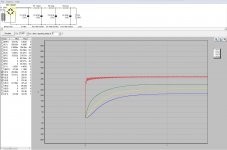
okay Stalker so I played around a little with the software you recommended and the attached jpeg is what I came up with assuming I use this transformer:
Allen Amplification - Parts Order Page
its the second one listed for $45. By your eyes ( or anyone else's that cares to take a look ) am I going about this the right way? Usually the values of the resistors increase as they move down the line away from the bridge rectifier, but in order to get the voltages i wanted, my resistors are 1.5k, 1k, 1k...usually it's something like 100, 1k, 5k, - am I doing something wrong or is this scheme okay? also, the transformer from the website only has 2A heater current... that's prob a lil low considering that the el84 needs around 800mA and the 6V6 needs around 650, add in the 2 12ax7s and i might be cutting it real close. This is one of the only transformers I could find that has at least 100mA on the HV tap and no 5v tap (because i don't need one) maybe I'm just making this out to be more difficult than it really is.. though the software is really nice to have so I can play around with things, i just want to make sure my approach is correct!
once again thank you for all the help you have given me, i'm sure this has taken up much more of your time than you would have liked but i've really been able to learn quite a bit in the process! 😀
Allen Amplification - Parts Order Page
its the second one listed for $45. By your eyes ( or anyone else's that cares to take a look ) am I going about this the right way? Usually the values of the resistors increase as they move down the line away from the bridge rectifier, but in order to get the voltages i wanted, my resistors are 1.5k, 1k, 1k...usually it's something like 100, 1k, 5k, - am I doing something wrong or is this scheme okay? also, the transformer from the website only has 2A heater current... that's prob a lil low considering that the el84 needs around 800mA and the 6V6 needs around 650, add in the 2 12ax7s and i might be cutting it real close. This is one of the only transformers I could find that has at least 100mA on the HV tap and no 5v tap (because i don't need one)
maybe I'm just making this out to be more difficult than it really is.. though the software is really nice to have so I can play around with things, i just want to make sure my approach is correct!once again thank you for all the help you have given me, i'm sure this has taken up much more of your time than you would have liked but i've really been able to learn quite a bit in the process! 😀
Attachments
Last edited:
- Home
- Live Sound
- Instruments and Amps
- EL84 and 6V6 in parallel???