Hi Dave,
I'm beginning to feel like one of those "Dummies for Windows" candidates!
Many thanks also for your very explicit description.
But my select file button says "browse"--I assume they're equivalent?
I browse, find my file, enter it, but nowt happens.
Guess I've not given up completely, as I've lodged this file on "flypicture", so will use that as well.
Kindest regards,
Ken
http://flypicture.com/display/NDc2NDU=
Attachments
Hi Anatoly,
Thanks for the fair comment.
Yes, it is a bit unusual, but works quite well on a couple of amps I've done. Will try and post a pic tomorrow, IF my server allows it.
The aim is minimizing exposure of inputs to other influences.
But could shield the cable from the rear I guess, as done before on other amps.
I'm not a professional you see, only build for my own pleasure,can do what might not suit a pro....
Besides which I'm trying to get as close as possible to Ian's description, which means placing inputs right alongside the input tube socket to keep earth leads short etc.
Regards,
Ken.
jackomancy said:I'm beginning to feel like one of those "Dummies for Windows" candidates!
You could always get a real computer <duck>
But that wouldn't help in this situation
jackomancy said:[Got me beat....
But you got it... both method 1 & method 2 in the same post.
dave
Hi Dave,
A Mac?? the Sony of PCs...
Yeah, but dunno how. Will try again with underneath shot.
Cheers and thanks,
Ken
http://flypicture.com/display/NDgyNzQ=
Edited to insert picture link and delete attachment - the mod team
You could always get a real computer <duck>
A Mac?? the Sony of PCs...
But you got it... both method 1 & method 2 in the same post.
Yeah, but dunno how. Will try again with underneath shot.
Cheers and thanks,
Ken
http://flypicture.com/display/NDgyNzQ=
Edited to insert picture link and delete attachment - the mod team
Hi Chris--this is a fantastic site--love all the helpful folk, plus can now post pix--tho last one a waste of folks time and space. Will delete and use a URL, and put up an update.
My Windoze is OK--it's the overloaded server[spammer email bombardment] that slows everything down....I believe there's a vista of something new.
Thanks for the kind words, it's still growing, but expect it will sound great, perhaps as good as my old Leak ST20!")
Ken.
PS Can't edit and delete,so here's the URL.http://flypicture.com/display/NDgyNzQ=
My Windoze is OK--it's the overloaded server[spammer email bombardment] that slows everything down....I believe there's a vista of something new.
Thanks for the kind words, it's still growing, but expect it will sound great, perhaps as good as my old Leak ST20!
Ken.
PS Can't edit and delete,so here's the URL.http://flypicture.com/display/NDgyNzQ=
jackomancy said:a vista of something new.
With Windows now running on the Intel Macs, i've taken to explore Windows. Before even thinking about Vista check out the license agreement as well as how they deal with content protection http://www.cs.auckland.ac.nz/~pgut001/pubs/vista_cost.txt
It is bloody scary....
dave
Dave--that Vista stuff is totally scary!Thanks for the tip-off.
I'll not touch it that's for sure.
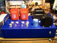
Here's the virtually finished amp interior.
Prelim testing before B+ application, for the powered boards.
These gave much grief due to fine iron tips,tremulous ageing hands and eyes, magnifying lenses and a short fuse.
I'm no newbie [over a dozen amps now mostly SE]but building this amp really tested my skills;could just be old age of course....
Will report on sound but distrust all such evaluations.
If it also impresses your mates on their speakers, you know it's a winner!
Cheers, and good luck to all Baby Huey builders.
Ken
I'll not touch it that's for sure.
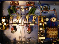
Here's the virtually finished amp interior.
Prelim testing before B+ application, for the powered boards.
These gave much grief due to fine iron tips,tremulous ageing hands and eyes, magnifying lenses and a short fuse.
I'm no newbie [over a dozen amps now mostly SE]but building this amp really tested my skills;could just be old age of course....
Will report on sound but distrust all such evaluations.
If it also impresses your mates on their speakers, you know it's a winner!
Cheers, and good luck to all Baby Huey builders.
Ken
Attachments
Hi all,
More .
.
Pride cometh before the fall.
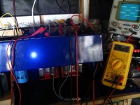
After all the hassle with the 803S tail boards, they finally worked. On powering up the B+, all there is, is a madly vibrating mains trans and an even more amazing indeed unbelievable
B+ of 87-93V, depending which rectifier [5R4WGT or5AR4/GZ34] is installed. This is a choke input PS, but adding an extra cap, ie making it a CLC pi filter, makes no difference.
It can only be the ancient trans as the choke' and 400uF cap are OK. First time this has happened for me.
Very weird as the trans looks good, unused I'm sure, delivers 425V per side as it should, but folds when asked to supply current.....has anyone a better explanation?
The amp works--here's some 1khz square waves. Each opt stage draws ~30mA. FR=3dB down at 30khz,6dB at 45khz,1dB at 10hz, but power output is ~1W. Overall feedback would improve this++. Built with a 33K crossfeed resistor only, as feedback.
This project is on indefinite hold until a new trans is sourced.
Profound apologies if undue hopes had been aroused...
More
.Pride cometh before the fall.
After all the hassle with the 803S tail boards, they finally worked. On powering up the B+, all there is, is a madly vibrating mains trans and an even more amazing indeed unbelievable
B+ of 87-93V, depending which rectifier [5R4WGT or5AR4/GZ34] is installed. This is a choke input PS, but adding an extra cap, ie making it a CLC pi filter, makes no difference.
It can only be the ancient trans as the choke' and 400uF cap are OK. First time this has happened for me.
Very weird as the trans looks good, unused I'm sure, delivers 425V per side as it should, but folds when asked to supply current.....has anyone a better explanation?
The amp works--here's some 1khz square waves. Each opt stage draws ~30mA. FR=3dB down at 30khz,6dB at 45khz,1dB at 10hz, but power output is ~1W. Overall feedback would improve this++. Built with a 33K crossfeed resistor only, as feedback.
This project is on indefinite hold until a new trans is sourced.
Profound apologies if undue hopes had been aroused...
Attachments
Hi all,
I'm new to tubes & recently came upon a working Rogers Cadet III amp http://www.diyaudio.com/forums/showthread.php?postid=1097002#post1097002
It works but I wanted to try & use the ECL86 tubes to better effect & build the baby Huey amp for a better sonic result. I may well use the Rogers chassis, transformers (both PS & output - although I know these are not the greatest) and probably try to the preamp section of the Rogers also (or Control Unit as it's called in the schematic)
I have a question for Ian - is the attached baby huey schematic the final version (no updates since)?
Thanks for your help
John
depending which rectifier [5R4WGT or5AR4/GZ34] is installed. This is a choke input PS, but adding an extra cap, ie making it a CLC pi filter, makes no difference
Jackomancy,
How are you pulling B+ from these tubes? Which pins are you tapping? These are very different tubes; they are not actually interchangeable. I tap the 5R4 at the CT of my 5V filament transformer.
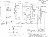
What DC voltage are you measuring after the rectifier but BEFORE the choke? You are setting your meter for DC and not AC, right?
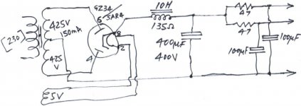
The 5R4 has a large voltage drop on load (~67V at 200 mA), more than the 5AR4 by far. You can use a SMALL initial cap (less than 4 muF) on the 5R4, and a little more on the 5AR4.
What value choke are you using, and at what current rating? What value are you using for a bleeder resistor after the choke at the large cap? (20KOhm for a 10H choke is good.) If you have any kind of short or low resistance across the PS output, you'll be pulling way more current and dropping the final B+ as well. Also, LC filters need a minimum draw to work well.
Could you describe your PS in detail for us? Maybe someone can spot an issue that's not related to the power trafo itself.
--Jeff
Re: Oops
That looks more like the ECL86 pre-cursor...
dave
jkeny said:Forgot to attach schema
That looks more like the ECL86 pre-cursor...
dave
Jeff Yourison said:
How are you pulling B+ from these tubes? Which pins are you tapping?
Jeff--I do believe you've put your finger right on the problem. On examining my own pix I can see I've carefully connected one HT lead to pin 3, when pin 4 is correct. I've been expecting FW performance from a halfwave setup. Double duh! Eyeballing the socket confirms it. Just hope the tubearen't damaged by this "elder" abuse....
Here you're not quite correct tho--they have the same socket connections, except the 5AR4 cathode also comes off pin 8. 5AR4 draws 1.9A, 5R4 2A, each pass 250mA max, but 5R4 has much higher max's often being used in transmitter service. Only used here to exclude 5AR4 as culprit.These are very different tubes; they are not actually interchangeable
True, on load being the point, in these circs the current draw is so small the 6-7V difference seems right.The 5R4 has a large voltage drop on load (~67V at 200 mA), more than the 5AR4 by far.
I'll do better and post a "schematic"[my PSUD won't print schematics--only the graph], exit B+ is 320-330V.The lynx-eyed will have noted the 150mA trans spec, but choke input allows 1.5X secondary current=225mA.Could you describe your PS in detail for us?
Many thanks again for your help--it is greatly appreciated.
There's another saying--no fool like an old one!
Cheers,
Ken.
Attachments
Hi, Ken,
Glad to have been of some (albeit oblique) help. I'm currently listening to both of those rectifiers plus others in building a tubed power supply for the El Cheapo amp worked out by Eli Duttman, Jim McShane and Dave of Planet10. I'm thinking of adding a few switching options to allow multiple rectifier choices.
I have found distinct sonic differences among the 5R4, 5AR4 and 5U4 in the El Cheapo (a well-designed p-p using 12AT7 and 12AQ5s). Relative to the original solid-state PS design, the 5R4 is nearly as detailed and yet bass heavy; the 5AR4 is a little more veiled and smoother, but slightly rolled off on both ends. The 5U4 is in-between and very nice over all. I've also tried using dual 6CA4s in parallel-anode mode (one on each secondary leg of the PT for better current handling), and this resulted in excellent detail but somewhat less bass output.
I'm too new to this to understand exactly what causes these differences, but I would guess that different tubes (and changes in the initial small caps) are affecting the impedance of the suppy from the amp's perspective. (Anyone have a response to this?)
Wishing you the best!
--Jeff
Thanks Dave (Planet10) Are you sure? Do you have a link to the latest?That looks more like the ECL86 pre-cursor...
I don't want to hijack this thread so if we need to discuss further I will start another thread
John
- Home
- Amplifiers
- Tubes / Valves
- EL84 Amp - Baby Huey