Hi JC Fardo,
Sorry for delay. I normally buy tubes and transformers in Brazil. Mult Comercial sells the most commum tubes and the PT, Choke and OPT I buy in Transformadores Lider. Lider makes customers wiring transformers according to your schematic/specification.
I have vintage speakers - Klipsch Heresy H-WO-12
Hammond 1650E freq.resp.
Hello again
About those outputtransformers.
I just bought them together with the recomended PS transformer and FYI there is a label on the transformer saying : 70hz - 50khz (no dB notation) On the carbon box there is another label saying 70 to 30khz +/- 1dB max.
They seem to have a lot of typos around Hammonds 🙄
🙄
Hello again
About those outputtransformers.
I just bought them together with the recomended PS transformer and FYI there is a label on the transformer saying
: 70hz - 50khz (no dB notation) On the carbon box there is another label saying 70 to 30khz +/- 1dB max.They seem to have a lot of typos around Hammonds
🙄A Baby Huey Tweak
I had a bit a mess with the Baby Huey last weekend.
Instead of taking the shunt feedback from the EL84 Anodes I changed it to take the balanced shunt feedback feeds from the Ultralinear Taps.
The Ultralinear Taps have 43% of the AC Voltage on them and also have a lower "drive" impedance. If anode to anode load is 8K then the maths say that the screen tap to screen tap drive impedance is 1500 Ohms.
Instead of 47K from each EL84 anode and 16 K as a cross connect to set feedback level I used 10K from each screen tap with a 9K1 (2 x 18K in parallel would do)as the cross connect. Measurements confirmed this gave identical feedback levels, sensitivity and output impedance.
That meant 20 V less DC drop in the feeds to the diffamp and I was able to increase the diff amp current by 100uA per side (Current Source upped by 200uA, that is, the CCS which was 1.2mA is now 1.4mA).
The increased diff amp current and the output transformer now being partly within the feedback loop I thought, gave worthwhile improvement. The sound seems a little better balanced across the frequency response. With the feedback off the EL84 anodes I thought frequency response was a little peaky at the high and low frequency extremes.
I also thought that detail was perhaps a little better.
Its a VERY easy and quick mod to try. Let me know if you try it and like it and particularly if you try it and don't like it.
Cheers,
Ian
Hi Ian,
I always look forward to your contributions on the Baby Huey topic.
Your idea of taking the shunt feedback from the UL-taps looks promising.
I'm eager to give this a try but as I'm still busy with house-building
my future "listening-room" is still a mess (Read: not shaped up for
critical listening). But I'll move my Fostex-Horns to this room in the next
days. If they don't require too much tweaking to adapt to the room,
i'll try your tweak.
PS: In my setup (mainly Full-range speakers + horns) I never whitnessed the peaky frequency response you describe (neither on the measurement-bench). I didn't use any zobels. Perhaps the horns flattened out the disturbing spectra. In fact the BabyHuey is very
balanced compared to the other SE an PP amps I built (and a lot cheaper too...).
PPS: What about your big triode (300B) project you mentioned some
time ago ?
Kind regards,
Yves
Hi Ian: I'm interested in trying this mod but I'm a little confused.
Am I removing the existing shunt feedback R and leaving the 47K anode load R's alone, replacing the 33R screen R's with 10K's and then cross connect a 9K1R between the 10k's? Which side of the 10K's does the new shunt R connect to?
thanks in advance!
Am I removing the existing shunt feedback R and leaving the 47K anode load R's alone, replacing the 33R screen R's with 10K's and then cross connect a 9K1R between the 10k's? Which side of the 10K's does the new shunt R connect to?
thanks in advance!
Boywonder,
Sorry for the confusion.
What you need to do is:
1) change the cross connect feedback set resistor from 16K (or whatever you were using) to 9K1
2) change the 47K resistors to the EL84 anodes to 10 K and at the same time shift the ends of these resistors which currently go to the EL84 anodes to go to the Ultralinear tap on the same push/pull side. Pick up these connections on the transformer side of the EL84 screen resistor. That is, leave the screen resistors and ultralinear taps wiring in place and just connect the 10K resistors to the UL tap to screen resistor junctions .
Hope this is clearer.
Cheers,
Ian
Yves,
Like you I'm in the middle of building - a purpose built electronics workshop. Concrete Slab is down.
The PPP300B amp still only exists on paper. Waiting on some chokes from Plitron to start this project.
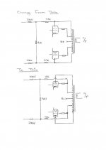
An updated schematic...
...would be very groovy and much appreciated. I'm also having trouble visualizing this change.
...would be very groovy and much appreciated. I'm also having trouble visualizing this change.
Ultimate EL84 design?
I see this as an ultimate EL84 design and I am considering to start building on...a few questions are present:
What transformers are recomendable of these:
http://www.hammondmfg.com/1608.htm
http://www.dynakitparts.com/store/product.aspx?id=237
or perhaps other better alternatives?
I see this as an ultimate EL84 design and I am considering to start building on...a few questions are present:
What transformers are recomendable of these:
http://www.hammondmfg.com/1608.htm
http://www.dynakitparts.com/store/product.aspx?id=237
or perhaps other better alternatives?
Skorpio,
Either of those will do. I've built Baby Huey's with:
Hammond 1608
Hammond 1650E
Vintage (Australian) A&R 4016 which were intended for a Mullard 5-10 design.
With a rail voltage of 300V you will get 10 Watts output and the Hammond 1608 will do. With rail vokltage at the high end (at say +350V) you will get around 12 Watts and something slightly "beefier" that the 1608 would help - marginally.
Cheers,
Ian
A weekend report.
Guys, The change discussed in post #563 and drawn in post #568 above were performed to my own latest Baby Huey which is the version with Source Followers show on the schematic at post #431 .
I was sitting down Friday night relaxing with an ale or two and listening to the amps with the shunt feedback changed to come off the ultralinear taps discussed above. Just listening to get an overall impression of whether that mod had made things better or not.
After a while I decided that there was something "muffled" about the sound. Was re-reading Allen Wright's Preamp Cookbook (whilst listening and drinking) when I got to the bit were he talked about subbing a 12AT7 for a 12AX7 in a phono section to drive the RIAA network and how it made a huge improvement because the increased current overcame some slewrate limiting of the 12AX7 trying to drive that same RIAA network.
Bingo - the lights flashed, if you look at that circuit (post #431 ) the source follower driving the EL84 output tubes has a 100K resistor to the negative rail. Some quick math - errr.. 45 less 12 volts across 100K gives 330uA - Thats seriously pathetic.
Grabbed the units and quickly soldered 47K across each 100K which gives about 33K and about 1 mA of current (increased current by X3).
I could hear the amps give a sigh of relief - most of that "muffledness" disappeared.
OK - Can we do better? Looking at my power supplies and the power ratings of the mosfet etc. I guessed I could take the current up a little more - also Allen (further on in the book) says cathode/source followers should be current source loaded.
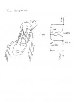
Back to the bench and made up 4 little sculptures (1.3mA Current Souces) to replace the resistors in the mosfet sources. See attachment for the CCS'es
Listen again - A complete transformation, the amps now sounded quite different, no "muffledness" but as well now sounded relaxed. It was the pace and rhythm that had improved out of sight (well sound anyway).
Having made this progress I will now have to re-assess the shunt feedback from the UL taps instead of the anodes mod.
Anyone who has built the post #431 circuit then ditch the 100K mosfet source resistors and fit the CCS'es shown below in their place. Do this BEFORE trying the anode to UL tap feedback source mod.
Morale of the Story:
1) Keep the driver currents up (I've run into the limit of my zener reg'ed +75V rail here but more current agian would probably be good).
2) CCS load cathode/source followers.
3) Hugh (AKSA) was right - see post #432
Cheers,
Ian
The Sculptures:
Guys, The change discussed in post #563 and drawn in post #568 above were performed to my own latest Baby Huey which is the version with Source Followers show on the schematic at post #431 .
I was sitting down Friday night relaxing with an ale or two and listening to the amps with the shunt feedback changed to come off the ultralinear taps discussed above. Just listening to get an overall impression of whether that mod had made things better or not.
After a while I decided that there was something "muffled" about the sound. Was re-reading Allen Wright's Preamp Cookbook (whilst listening and drinking) when I got to the bit were he talked about subbing a 12AT7 for a 12AX7 in a phono section to drive the RIAA network and how it made a huge improvement because the increased current overcame some slewrate limiting of the 12AX7 trying to drive that same RIAA network.
Bingo - the lights flashed, if you look at that circuit (post #431 ) the source follower driving the EL84 output tubes has a 100K resistor to the negative rail. Some quick math - errr.. 45 less 12 volts across 100K gives 330uA - Thats seriously pathetic.
Grabbed the units and quickly soldered 47K across each 100K which gives about 33K and about 1 mA of current (increased current by X3).
I could hear the amps give a sigh of relief - most of that "muffledness" disappeared.
OK - Can we do better? Looking at my power supplies and the power ratings of the mosfet etc. I guessed I could take the current up a little more - also Allen (further on in the book) says cathode/source followers should be current source loaded.
Back to the bench and made up 4 little sculptures (1.3mA Current Souces) to replace the resistors in the mosfet sources. See attachment for the CCS'es
Listen again - A complete transformation, the amps now sounded quite different, no "muffledness" but as well now sounded relaxed. It was the pace and rhythm that had improved out of sight (well sound anyway).
Having made this progress I will now have to re-assess the shunt feedback from the UL taps instead of the anodes mod.
Anyone who has built the post #431 circuit then ditch the 100K mosfet source resistors and fit the CCS'es shown below in their place. Do this BEFORE trying the anode to UL tap feedback source mod.
Morale of the Story:
1) Keep the driver currents up (I've run into the limit of my zener reg'ed +75V rail here but more current agian would probably be good).
2) CCS load cathode/source followers.
3) Hugh (AKSA) was right - see post #432
Cheers,
Ian
The Sculptures:
Attachments
Hi,
Love the Sculpture!
I'd been following this thread for a while now, love your work here. I've been collecting bits for the latest UL Baby Huey, was considering using an existing 8k pp opt for the job but eventually changed my mind to go for the full blown UL opt.
I'd build a few SETs with minimum SS parts as I'm great when making sand smoke . Since I am more more of a P2P guy, I got all fired up to start a baby huey build when I see the Sculpture.
Can the Sculpture replace the LTP CCS?
what is the math's for setting the Sculpture current?
Cheers
Ken
Love the Sculpture!
I'd been following this thread for a while now, love your work here. I've been collecting bits for the latest UL Baby Huey, was considering using an existing 8k pp opt for the job but eventually changed my mind to go for the full blown UL opt.
I'd build a few SETs with minimum SS parts as I'm great when making sand smoke
. Since I am more more of a P2P guy, I got all fired up to start a baby huey build when I see the Sculpture.Can the Sculpture replace the LTP CCS?
what is the math's for setting the Sculpture current?
Cheers
Ken
Hi. I`m considering building this amp but have a pair of Hammond 1620s on the bench. Can i use these? I know they are not ideal but i`d like to use the parts i have if possible.
Cheers, Steve.
Cheers, Steve.
Audio_idiot said:what is the math's for setting the Sculpture current?
It's just your basic ring of two CCS (I prefer cascoded BJTs, but oh well). The current is determined by the 499R emitter resistor. Since this is connected across the BE junction of the second BJT, it always has 0.6Vdc across it. Since you have two Vbe drops at the bottom of the 220K bias resistor, that voltage is 1.2Vdc more positive than the design nominal voltage at "purple". Take the voltage at "blue" and subtract to determine the necessary voltage drop for that resistor. Figure that the current through the bottom 2N5551 will be ten times or more (within reason) of the base current of the bottom 2N5551 and you've got everything you need to design one for yourself.
Be aware that the ring of two is liable to instability, and watch out for possible oscillation (reason for the 100R base stopper).
Hi Guys,
Audio_Idiot
- Miles has given you the maths for the the current of the CCS. He has also given you some good advise when saying he prefers a cascoded BJT CCS to a Ring of 2 "Scuplture". So do I. A very early Baby Huey did have a "Ring of 2"CCS in the tail of the diff amp and replacing it with a Cascode BJT CCS did improve things. They are still used in the EL84 Cathodes of the CCS biased Baby Huey as they are "good enough" for that task.
The Ring of 2 circuit is handy when you want to knock up a little "Scupture" to replace a resistor as was the case here. Now that I know that is the way to go I will at some stage rebuild that section with a proper Cascode BJT CCS and try running current at say 3 or 4 mA to see if that gives further improvement. I have to rebuild my + 75V rail first as it currently won't handle the extra current (it is zener regulated). An alternate idea, which I will look at, is to use a "bootstrap" MOSFET on top of the Current Source loaded Source Follower (a.k.a. a SS version of Allen Wrights's SLCF) which can then be run from the main B+ rail without any need for the +75V rail.
Aside: The "Ring of 2" CCS is handy when you don't have much voltage to play with (Compliance Voltage). Most recently I used them in a pair of Audio Space AS-6M 300B Push Pull Monoblocks which came to me for a "Spiff Up". They used a 6SL7 Paraphase Splitter (which was badly balanced - corrected) followed by a 6SN7 ALMOST Diff Amp Driver (I say "almost" due to 2K2 as the tail resistor). Replacing that 2K2 with a ring of 2 CCS made a huge difference to those amps. These things were typical of a lot of stuff coming out of China - a poor implementation of an average circuit borrowed straight out of the 1960's and showing little or no understanding of how those circuits operate. Changing 1 resistor to balance the paraphase splitter and adding the CCS to the diffamp driver tail and stripping out a totally unneccessary 3u3 electrolytic coupling capacitor lifted the performance of those amps by an order of magnitude (x10). Of course stripping it and rebuliding to a different circuit would have been even better but that was beyond the scope of what was wanted by the owner.
Castlesteve
- You can indeed use the Hammond 1620, The 6600 Raa spec is not ideal BUT in tube circuits a change of 20% in "ideal" values rarely makes a "rodents hind quarters".
Cheers,
Ian
Hi Ginger, Miles,
Thanks for the insight, I'm now clear with the Ring of 2 CCS maths and its characteristics. I will try to replace on of my catode resistors with it as experiment, hope the SS smoke god will spare me in this test.
I'd came accross some Cascoded BJT in my reading but I'm totally confused, I guess I'll have to look up to your work here and try my best to learn as it goes...
Another question. How about the Gyrator circuit to replace choke? could you kindly show me a working circuit for the Baby Huey?
Cheers
Ken
Audio_idiot
Yes a gyrator to replace the choke is something I'm looking at - its not ready.
There are 2 Baby Hueys
The definitive one is the 1st one and you can find the schematic at post #9
The 2nd on eis the fixed biased variant which is the schematic at post #431. Thats what I'm working on now.
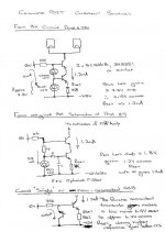
CCS are just a transistor circuit where you clamp the voltage across the Rset in the emitter of the transistor usually by clamping the base voltage using a LED as a voltage reference or similar.
The single transistor CCS has an output impedance (the measure of a CCS's "goodness") limited by Early Effect. Early was the gezzers name, nothing to do with things happening before you expect.
Yoi can improve the single transistor CCS in 2 ways - 1st use as high a reference voltage as you can. the output impedance is effectively the Rset or emitter resistor multiplied by the transistor beta. A higher voltage means you can use a higher Rset and hence more Zout.
The 2nd (and better) way to improve it is put another transistor on top (cascoded).
Here are some scribbles for your edification - all do the same 1.2mA current source. Top to bottom is best to worst BUT all off these are probably better than the ring of 2 circuit.
Cheers,
Ian
Yes a gyrator to replace the choke is something I'm looking at - its not ready.
There are 2 Baby Hueys
The definitive one is the 1st one and you can find the schematic at post #9
The 2nd on eis the fixed biased variant which is the schematic at post #431. Thats what I'm working on now.
CCS are just a transistor circuit where you clamp the voltage across the Rset in the emitter of the transistor usually by clamping the base voltage using a LED as a voltage reference or similar.
The single transistor CCS has an output impedance (the measure of a CCS's "goodness") limited by Early Effect. Early was the gezzers name, nothing to do with things happening before you expect.
Yoi can improve the single transistor CCS in 2 ways - 1st use as high a reference voltage as you can. the output impedance is effectively the Rset or emitter resistor multiplied by the transistor beta. A higher voltage means you can use a higher Rset and hence more Zout.
The 2nd (and better) way to improve it is put another transistor on top (cascoded).
Here are some scribbles for your edification - all do the same 1.2mA current source. Top to bottom is best to worst BUT all off these are probably better than the ring of 2 circuit.
Cheers,
Ian
Attachments
gingertube said:Audio_idiot
Yes a gyrator to replace the choke is something I'm looking at - its not ready.
CCS are just a transistor circuit where you clamp the voltage across the Rset in the emitter of the transistor usually by clamping the base voltage using a LED as a voltage reference or similar.
Yoi can improve the single transistor CCS in 2 ways - 1st use as high a reference voltage as you can. the output impedance is effectively the Rset or emitter resistor multiplied by the transistor beta. A higher voltage means you can use a higher Rset and hence more Zout.
The 2nd (and better) way to improve it is put another transistor on top (cascoded).
Cheers,
Ian
Will it be better if we attach a string of led to give higher reference voltage accross the Rset?
Ian,
You wrote:
>An alternate idea, which I will look at, is to use a "bootstrap" MOSFET on top of the Current Source loaded Source Follower (a.k.a. a SS version of Allen Wrights's SLCF) <
From my experience it will sound UGLY! If youbootstrap, it must be with a tube. MOSFETs anywhere near the signal path have a sound that I cannot accept, possibly due to their input capacitance varying with signal level, in a non linear manner.
If you want to use my circuits, best you use the good ones...
Regards, Allen (Vacuum State)
Hi Ian,
good to hear that the CCS loaded SF was an improvement.
As you know AllenW prefers the full blown SLCF so I will be interested to see how your bootstrapped SF turns out. Thru one of the forums Allen advised he doesn't use mosfets anywhere now preferring an all tube CCs and bootstrapping, though did advise that his Ozzie 'partner' (Joe Rasmussen) found bipolars in a darlington set-up very good. Could be worth a phone call to bounce ideas back and forth.
All your postings are much appreciated.
tim
- Home
- Amplifiers
- Tubes / Valves
- EL84 Amp - Baby Huey