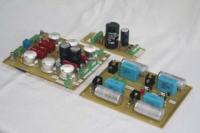
Here is my Baby Huey built in three modules: PS, Bias & CCS and Main. I just finished the modules wiring and I din't test nothing to see if is working. I have a chassis recovered of an old nec inverter that I will try to use to assembly the amplifier. I'll use ECC803 and EL84 both from JJ.
Photo all modules:
Photo all modules:
Attachments
Hi, Akirasugai
I found JJ 12ax7 were not that good..the last pair I got, one suffered from microphonic wooooo.., the other one was noisy.
I hope the ones you are going to get (ECC803) are not the same JJ 12AX7..
and,
JJ EL84, I found them were very decent, good bass.
JueiC
I found JJ 12ax7 were not that good..the last pair I got, one suffered from microphonic wooooo.., the other one was noisy.
I hope the ones you are going to get (ECC803) are not the same JJ 12AX7..
and,
JJ EL84, I found them were very decent, good bass.
JueiC
G'Day, Akirasugai,
I have had my Baby Huey up and running for a little while now. I am really loving it. My main amp was a TubeLab SimpleSE. I put Baby Huey in to the main system, and have not felt the need to take it out! My main speakers are set up for bi-wiring, so I may end up using the SimpleSE to drive the tweeters and the Huey for the woofers.
I hope that you like your amp as much as I do!
I am still rather new to this hobby, so take my next comments with that in mind... My first scratch built amp was a little ambitious. I tried to put too much in too small a space and I had a poor understanding of correct wiring/grounding techniques. It hummed and buzzed! I am now very cautious with signal, heater and ground/zero volt wiring. Your main amp board looks very neat, but I am a little worried that you might be setting yourself up for a noisy amp.
It is a little difficult to see, but it looks like your heater wiring is very thin, and running as two parallel wires. Remember, the EL84s draw about 760mA each and the ECC83 will draw about 300mA, that is almost 2A total. Unless you are running DC heaters, tightly twisted wiring tucked in to the corner of the chassis gives the lowest noise. Also looks like you have lots of wires running parallel to your HV. This can also induce noise.
I would suggest hooking everything up before you start drilling holes in a chassis. If my fears are unfounded and all is OK, then congratulations on a very neat job! If you do get some noise, then perhaps the areas I mentioned might be a good place to start trouble shooting.
Once again, hope your project works out well and you enjoy it as much as I like mine!
Cheers,
Chris
Hi jueic,
Thanks a lot for your advise. I have a pair of both JJ ECC803 and Electro-harmonix 12 AX7. I'll try both to see the best performance.
Thanks a lot for your advise. I have a pair of both JJ ECC803 and Electro-harmonix 12 AX7. I'll try both to see the best performance.
Hi Ian,
I built the original Baby Huey with ECL86 and love the sound! Not wishing to drag you back to this project as you have moved on but would fixed bias be feasible with ECL86 version?
I built the original Baby Huey with ECL86 and love the sound! Not wishing to drag you back to this project as you have moved on but would fixed bias be feasible with ECL86 version?
Hi Chris,
Thank you very much for your clear comments/advises!
Yes, probabily I'll get some hum because,as your
comment, parallel heater wiring is not recomended
despite of short lenght - mine is more than 10 cm.I can
easyly re-wiring with twisted pair if necessary. I used
for heater, tinned copper 24AWG (0.5mm) and you are
corrected, it's not enough to heater 2 EL84 and 1 ECC803 - thanks! I will change to 22 or 20AWG that will support 2 or 3A.
Akira
gingertube said:raidprotector,
I am very impressed with your build method.
Keep us informed of your progress.
Best Wishes
Ian (Gingertube)
P.S.
For those who have built a version of this amplifier using current sources in the output tube cathodes with bypass capacitors, here is another experiment for you to try:
Have a look at what Allen Wright did on this amp:
An externally hosted image should be here but it was not working when we last tested it.
Notice that the 0V side of the cathode bypass capacitors do not go directly to 0V. The 2 0V ends of the capacitors are connected together and then have a 68 Ohm resistor to 0V. You can try this on a "Baby Huey". The fact that we use current sources rather than fixed resistors for the cathode biasing will not make any difference to this scheme.
This is a 3rd harmonic distortion suppression scheme and it is worth trying on a "Baby Huey". Try resistor values of between 33 ohms and about 150 ohms (use 2 watt resistors) to see what sounds best. You are listening for a smoother, less "Edgy" sound, particularly at higher frequencies. And of-course, let us know if you think it makes any difference, and if so, what resistor value sounds best to you.
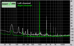
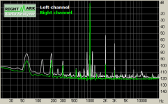
Finally got around to trying this on my 6CK4 amp. It has a CCS under the LTP splitter/driver, but is direct coupled with no feedback. Don't think those differences should matter qualitatively. My output cathode resistors are 3k bypassed with 220uf. I used a pot to tune for the extra resistor. I found a distinct minimum at about 400R. Interesting that this ratio (0.13) is very close to what Allen shows (0.14). Here's with the resistor. Next post is without.
Attachments
Sheldon,
Thanks for your feedback.
The Baby Huey with approx 40mA current sources in the output tube cathodes is roughly equivalent to running 270R cathode bias resistors.
Based upon the 0.13 or 0.14 ratio that would suggest using a 36 Ohm resistor. Notes I have from another source say the null is reasonably broad so 33 or 39 Ohms would do.
Cheers,
Ian
Ian,
At the risk of looking like a bit of a dill, where do you put the resistor with the constant current source, between the source and ground? Is it that simple?
Cheers,
Chris
At the risk of looking like a bit of a dill, where do you put the resistor with the constant current source, between the source and ground? Is it that simple?
Cheers,
Chris
Chris,
Each Output tube current source has a bypass capacitor. Disconnect the -ve (0V) ends of these bypass capacitors but leave them joined together. Then add a single 33 Ohm between the bypass capacitors -ve terminals and the old 0V connection point.
Let us know if, like Sheldon, you think it makes a difference.
Cheers,
Ian
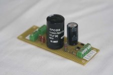
Hi Akira
That is a compact layout...I just hope that the capacitors between the EL84's don't get too hot...there is quite a lot of warmth there (48W plate dissipation + ~20W in heaters)
Maybe you already thought about it, but anyway...I would use some longer screws to hold the sockets, and use those screws to bolt the whole module to the chassis...that way you won't apply strain to the fragile PCB when inserting or pulling your tubes.
Saudações de um brasileiro erradicado 😀
Erik
Hi Erik,
Thanks a lot for your comments. Yes I'm afraid too concern to heat in capacitors. I'll thinking in your sugestion, my difficult is the limited height due the chassis top cover.
Thanks again
Muito obrigado!
Thanks a lot for your comments. Yes I'm afraid too concern to heat in capacitors. I'll thinking in your sugestion, my difficult is the limited height due the chassis top cover.
Thanks again
Muito obrigado!
gingertube said:Sheldon,
Thanks for your feedback.
The Baby Huey with approx 40mA current sources in the output tube cathodes is roughly equivalent to running 270R cathode bias resistors.
Based upon the 0.13 or 0.14 ratio that would suggest using a 36 Ohm resistor. Notes I have from another source say the null is reasonably broad so 33 or 39 Ohms would do.
Cheers,
Ian
Even more striking than the reduction on odd order harmonics is the complete elimination of the side bands around the 1kHz fundamental. That seems real, as it's repeatable, even at half the resistor value. Any explanation for that?
Sheldon
Sheldon said:
Even more striking than the reduction on odd order harmonics is the complete elimination of the side bands around the 1kHz fundamental. That seems real, as it's repeatable, even at half the resistor value. Any explanation for that?
Sheldon
That struck me too. The ellimination of "sidelobes" from intermodulation with 120Hz PS ripple, especially on the left channel.
Also notice that the right channel shows almost total suppression of 120Hz ripple, independent of the bypass arrangement. Probably due to almost perfect balance.
Svein.
Svein_B said:
That struck me too. The ellimination of "sidelobes" from intermodulation with 120Hz PS ripple, especially on the left channel.
Also notice that the right channel shows almost total suppression of 120Hz ripple, independent of the bypass arrangement. Probably due to almost perfect balance.
Svein.
Sorry, I should have noted that the green trace is the soundcard reference - it had better be decent. I'm only measuring one amp channel per trace - some channel in both cases, thought the results were the same for the other channel.
Sheldon
- Home
- Amplifiers
- Tubes / Valves
- EL84 Amp - Baby Huey