I bought a cheap amplifier kit from Hong Kong and have been sent the schematic in advance of the hardware.
I'd be very grateful if the more knowledgable inmates could offer any feedback on the design or possible improvements that could be made.
I plan on upgrading the coupling caps (larger teflon or PIO) and possibly changing to LED cathode bias (this worked a treat in my Hawthorne Spud).
I'd be very grateful if the more knowledgable inmates could offer any feedback on the design or possible improvements that could be made.
I plan on upgrading the coupling caps (larger teflon or PIO) and possibly changing to LED cathode bias (this worked a treat in my Hawthorne Spud).
Attachments
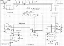
Not sure I understand their approach. Fancy VAS/driver stage feeding a pentode mode EL34 with no feedback?
The SRPP first stage is probably just a fashion statement. The pentode EL34 output will make it sound like a rather loud but well-mannered 1950's wireless set. Perhaps they originally intended to run it in triode mode, but then found it had too little output?
Sorry, but you did ask for our opinion!
Sorry, but you did ask for our opinion!
That's very helpful - please criticise all you like!
I'm keen to rejig the circuit as required to give best sound quality with these tubes and transformers. Power output is not important (I already have a 2-3W spud amp, and high efficiency speakers to match).
Any advice would be much appreciated 🙂
I'm keen to rejig the circuit as required to give best sound quality with these tubes and transformers. Power output is not important (I already have a 2-3W spud amp, and high efficiency speakers to match).
Any advice would be much appreciated 🙂
As the other posters have indicated, it's a POS. 🙁
The easiest way to make something out of that dog pile is to disconnect the EL34 screen grids from B+ and tie them, via 100 Ω resistors, to their respective anodes. The result is triode mode, which will have tolerable (hopefully acceptable) characteristics in the distortion and damping factor departments. Power O/P will be 4 or so WPC.
The easiest way to make something out of that dog pile is to disconnect the EL34 screen grids from B+ and tie them, via 100 Ω resistors, to their respective anodes. The result is triode mode, which will have tolerable (hopefully acceptable) characteristics in the distortion and damping factor departments. Power O/P will be 4 or so WPC.
As the other posters have indicated, it's a POS. 🙁
The easiest way to make something out of that dog pile is to disconnect the EL34 screen grids from B+ and tie them, via 100 Ω resistors, to their respective anodes. The result is triode mode, which will have tolerable (hopefully acceptable) characteristics in the distortion and damping factor departments. Power O/P will be 4 or so WPC.
Reasonably well executed, a 4 watt triode connected EL34 P/P is not to be sniffed at, but as originally configured this "kit" might well be considered as organ donor for a complete redesign.
Eli - would a CCS loaded version of the 12AT7 LTP driver stage from your and Jim's El Cheapo design drive a pair of EL34? What I know for sure (courtesy of Eddie Vaughn) works "well enough" is a WE417 / Raytheon 5842
Last edited:
What about pseudo-UL? Put two resistors across the OPT primary, with their junction taken to g2. Could this match the existing transformer better than full triode mode?
Eli - would a CCS loaded version of the 12AT7 LTP driver stage from your and Jim's El Cheapo design drive a pair of EL34?
There's enough gain to drive no NFB triode wired EL34s. For an EL34 circuit with NFB, gain is insufficient.
What about pseudo-UL?
That requires a buffering voltage follower of some kind. You be sure that the Chinese guano is on a PCB and not P2P wired.
Last edited:
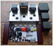
Thanks guys. The 'amp kit' is basically a set of tubes, drilled chassis and transformers with schematic and token cheap components. As it's point to point, I'm completely happy to go with a completely different scheme (whatever is recommended by you chaps).
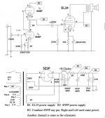
Looks like it might be quite easy to build a version of the SRPP Eli & Ezequiel recommend in this thread: http://www.diyaudio.com/forums/tubes-valves/154796-el34-se-amp-schematic.html
What would I need to do to accomodate the 6N9P/6SL7 instead of the 12AU7?
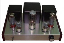
Here are some photos of the kit:
Looks like it might be quite easy to build a version of the SRPP Eli & Ezequiel recommend in this thread: http://www.diyaudio.com/forums/tubes-valves/154796-el34-se-amp-schematic.html
What would I need to do to accomodate the 6N9P/6SL7 instead of the 12AU7?
Here are some photos of the kit:
Attachments
Last edited:
It seems I'm the proverbial "Monkey's Uncle". 🙄 That kit appears to be (very happy surprise) P2P.
As rmyauck stated, you can substitute a 6SN7 for the 12AU7 in the SRPP setup with zero parts value changes. Current production ElectroHarmonix and "reissue" TungSol 6SN7s are affordable and have quite respectable sonics.
Don't be surprised if the rectifier arcs over at start up. 🙁 The Chinese 5z3p is supposed to be an equivalent of the U.S. 5U4G. However, I've lost count of the number of people needing assistance with arcing. If the tube gives you trouble, a GE 5U4GB (either strong used or NOS) will resolve the issue, without sending you to the poorhouse.
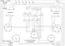
Interesting in the layout diagram shows a 27K resistor connecting the output to the cathode of the 6sn7, presumably an NFB scheme like in a Williamson amplifier. Yet the circuit diagram does not show this. The constant current fed VAS stage reminds me of a transistor amplifier. If you could pick up a decent output transformer cheap it might make a good basis for a mono PP amp.
Many thanks for the help - I've decided to go with the SRPP 6SN7 EL34 circuit.
The schematic shows a transformer with 230VAC secondary and solid state rectification for the B+ supply, with B1=278V and 268V at the EL34 anode.
The transformer I plan on using has dual 330VAC secondaries. I plan on using the 5Z3P for rectification, and will have two 10H chokes available for use if required (with 10uF oil cap between 5Z3P and choke and 200uF MKP after the choke). Even with the valve rectifier and larger choke, I'm sure the B1 voltage will be much higher than the 278V required for the circuit.
Would it be sensible to use an additional LC filter stage with a second 10H choke to reduce the voltage?
Rather than raise the supply impedance by adding additional RC filters to drop the B+ voltage, could I just use a higher voltage for the EL34 and change the cathode resistor and cathode bypass cap accordingly to keep the EL34 happy?
The Tubelab Simple SE page lists different combinations of output transformers, B+ voltages and cathode resistors for the EL34: Tubes & Transformers
Can I just infer a suitable cathode resistor and bypass cap using this list then measure current etc. to ensure the EL34 is not dissapating too much power?
I will be able to get the voltages required for the 6SN7 by increasing the 4.7K resitors as required.
I bought a cheap amplifier kit from Hong Kong and have been sent the schematic in advance of the hardware.
I'd be very grateful if the more knowledgable inmates could offer any feedback on the design or possible improvements that could be made.
I plan on upgrading the coupling caps (larger teflon or PIO) and possibly changing to LED cathode bias (this worked a treat in my Hawthorne Spud).
I'm looking at one now. Has anyone built this? Did it work?
I'm not sure about B3 and where it should be connected if at all. One drawing shows B3 connected. Another drawing shows B3 not connected at all.
Is this thing worth troubleshooting? Thanks in advance.
I'm looking at one now. Has anyone built this? Did it work?
I'm not sure about B3 and where it should be connected if at all. One drawing shows B3 connected. Another drawing shows B3 not connected at all.
Is this thing worth troubleshooting? Thanks in advance.
Do you mean that you are looking at an actual kit you have built, or that you are looking at the diagrams/schematics?
John
Do you mean that you are looking at an actual kit you have built, or that you are looking at the diagrams/schematics?
John
The amp has been built but is not working properly. Has anyone built one as per the drawings that has worked?
Thanks
Greg
B3 is used to bias the heater supply for the first stage. This ensures that the rated heater-cathode voltage is not exceeded. However, the amp would probably work either way, but you might get some hum or noise.
The amp has been built but is not working properly. Has anyone built one as per the drawings that has worked?
Thanks
Greg
There is a thread 'on the go' over at AudioKarma right now on the same topic. (Here is a better place, I know, but...)
You might want to drop in to that discussion:
Trouble with a DIY EL34 Tube Amp Kit - Page 2 - AudioKarma.org Home Audio Stereo Discussion Forums
John
My curiosity ("How bad can it be?") overcame my common sense and I bought one of these kits. It arrived a few days ago.
For any future readers of this thread: STAY AWAY!!!!
The chassis is stainless steel - one of the nastiest materials to work with if you aren't properly equipped.
The hole for the PT isn't cut at all, the transformer mounting holes are 'off' and the OT flange is bigger than the cover provided. No grommets provided (or used in the build pictured on eBay) so those OT wires (@300+ vDC) going through the chassis could provide some excitement, in time.
The nuts don't match the machine screws, so you need to find your own (4-40) fasteners for the tube sockets.
And, as noted above, the schematic and the layout diagrams don't match- a minefield for a beginner.
I'll be hitting the parts box for replacements for some of the electronic bits as well. Very low-end looking parts, in general.
...on and on......
I'm going to try building the Ezequiel-recommended circuit (Thanks, Eli, Ezequiel) and I'll let y'all know how it works out.
The old saying about sow's ears and silk purses is ringing in my head!
John
The old saying about sow's ears and silk purses is ringing in my head!
Or lipstick on a pig.😀
jeff
- Status
- Not open for further replies.
- Home
- Amplifiers
- Tubes / Valves
- EL34B 6N9P 5Z3P amplifier kit - any thoughts on schematic?