billr said:yes the 70v winding will do for biasing, biasing takes no current, except for a pew picoamps, so you are fine.
wish you well in what you are doing.
I thought Ia was the bias curent! Sorry. I am an idiot but willing to learn.
SY said:I'm an administrator, so I have to be around!😉 .
Geez. I better be careful how many stupid questions I post.
Ia is the current that flows up from the cathode through to the anode.
If you are using auto bias, ie, a resistor in the cathode of the valve, Rk, then the Ia will drop a voltage across it. If your grid is effectively at 0v, as it will be if driven via a cap from the preceeding stage and with a Rg to ground, then the grid will effectively be Ia * Rk more negative than the cathode, as the cathode has been 'lifted'.
If on the other hand you are using fixed bias, in this case there will be little or no Rk, and you will be injecting a negative bias voltage into the grid. Again, this has to be protected via a cap from the previous stage. Directly applied negative bias to the grid draws pico amps.
I hope that this makes it clear for you.
kind regards
bill
Sorry I should have added that, the case i mentioned above is for a triode, for pentodes and similar devices, for auto bias you also have to add the current drawn by the suppressor grid to correctly determine the bias drop.
again, kind regards
bill
again, kind regards
bill
bill,
very informative post. 😉 thanks!
navin,
how's it coming? any news on your parts collection?
cheers,
JojoD
very informative post. 😉 thanks!
navin,
how's it coming? any news on your parts collection?
cheers,
JojoD
Ia is the current that flows up from the cathode through to the anode.
maybe what you actually meant was electrons flow from cathode to anode, and electrical current by convention flows from plate to cathode.
JojoD818 said:navin,
how's it coming? any news on your parts collection?
ran into a problem with the power transformer. He could not supply me a size that fit my existing cabinet so I have to re work my cabinet.
beyond that I am still looking for 10nf/3KV and 100nf/630V caps.
navin said:
ran into a problem with the power transformer. He could not supply me a size that fit my existing cabinet so I have to re work my cabinet.
beyond that I am still looking for 10nf/3KV and 100nf/630V caps.
If you were just my neighbor I could have helped you with your transformer. 😀 Hey, fitting something into something that seems impossible to fit is why DIY is exciting. 😀
I am working on getting some Allen Bradley resistors for my amp, but if it proves too hard to get then I'll just use my stock carbon films. Just finished my timer and relay boards. 😎
good luck on your parts hunt.
JojoD
JojoD, stay away from Allen Bradley, i have a carton full of them with different values and have to say they have serious value drift! For example, 390R now is only 330R, 1M now 900K! Yikes! My metal film from Mouser are really good as well as some Kiwame (bit pricey, but quality!)
arnoldc said:JojoD, stay away from Allen Bradley, i have a carton full of them with different values and have to say they have serious value drift! For example, 390R now is only 330R, 1M now 900K! Yikes! My metal film from Mouser are really good as well as some Kiwame (bit pricey, but quality!)
Yikes! Are you sure your DMM is working properly? I mean those off-value drifts won't destroy my amp but can seriously affect the way the circuit works.

Maybe another reason to save money and use my stocks of 2w carbon resistors then?
JojoD818 said:
Yikes! Are you sure your DMM is working properly? I mean those off-value drifts won't destroy my amp but can seriously affect the way the circuit works.
Maybe another reason to save money and use my stocks of 2w carbon resistors then?
you could addd 10% to the values! 🙂
navin said:
you could addd 10% to the values! 🙂

that's not a very practical idea. 😀
oh and layout looks good to me. 😉
JojoD818 said:
that's not a very practical idea. 😀
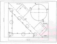
it was in jest! you dont think the OPT and PS are too close?
navin said:
it was in jest! you dont think the OPT and PS are too close?
Nice design! It is original and I like it.
And yes, I think at the OPT and PS are too close. But it is only what I think, practice can differ. I always made a prototype fefore building the final amp. It is relatively cheap metal boxes for prototype work. It must be high enough and big enough. What I do on the prototype is to fix 4 metal corners high enough to be able to put the amp upside down and work on it, without at the tubes or the trannies touch the table.
The advantage of a prototype is at it goes very fast to build the amp. You don't have to pay attention to the look and can focus on the functionalities. If the box is big enough, it is very easy to do modifications or to add or deplace a circuit, whatever you want or have to try.
Even someone as me make prototypes. I have both a good theorical knowledge and practical experience in electronic, from tubes to dsp processor, and from audio to high frequency, but after at I have calculated a circuit, even the simplest one, I make a prototype and I test it.
Without theoritical knowledge, you have to rely on someone else for the circuit, but the implementation is very important. In high frequency, the implementation is even a part of the circuit. Electron tubes are almost magic devices, because they are at the frontier between electromagnetism and electronic (It is why I lke it!). How the circuit work is electronic, but how the tubes work is electromagnetism. How a tranny work is electromagnetism.
You must have a goal when designing an amp. If you want to do the better amp you can made, you must have 3 boxes, one with the PS, the redressor and the first caps of the power supply (it is strong electrical flux in those caps), one with the amp, and one with the preamp.
If you want to compromize, you can have the whole thing in one cabinet.
But in all cases, only when testing the amp, you will know if it is doing what you want. It is why I do prototypes, they are more easier and faster to modify as the final amp.
Dominique_free said:
Nice design! It is original and I like it.
And yes, I think at the OPT and PS are too close.
The advantage of a prototype is at it goes very fast to build the amp.
You must have a goal when designing an amp. If you want to do the better amp you can made, you must have 3 boxes, one with the PS, the redressor and the first caps of the power supply (it is strong electrical flux in those caps), one with the amp, and one with the preamp..
1. what do you like? original might not alwyas be good. i think that the gurus out here must have already covered all possible good ideas.
2. this is a prototype. I am going to make this first on a steel sheet to see if all fits and then in a real cabinet.
3. i already have a seperate crossover/preamp box with steve becnh's ECC88 crossover. I can see one option...a 4 box design.
box 1: preamp and crossover
box 2 and 3: power amp circuit
box 4: 2 Power supply transformers.
that idea was my plan B.
navin said:3. i already have a seperate crossover/preamp box with steve becnh's ECC88 crossover. I can see one option...a 4 box design.
that idea was my plan B.
If you don't try the 3 box option, you will never know if it is good enough or not. In my 807 guitar amps, they have a very high sensitivity (~1.7 mV for full output), and I have all in the same cabinet. The PS is in one corner and the OPT in the other corner (not exactly, but almost).
The noise I get is a white noise, and that even at full volume. It was some hum with the first version, but to put a DC supply for the heaters removed it completly.
Perhaps just a general reassurance regarding the closeness of transformers, though not to be literally followed in practice!
I have recently built a 100 + 100W tube amplifier with 3 fairly large transformers mounted side by side for practical reasons. The transformers measured 14 x 14 cm with 10 cm height (canned) - the cores were 6 cm thick (stack). They were boxed and had no more than 2 mm space in between, and worse, they could not be mounted at core right angles; they all lay in the same position! There were 2 output trannys with the power one in between.
Folks thought I was crazy and I too expected the worst, but the hum contribution in the end from the layout alone was negligible. One advantage was that they were C-core. It must also be added that passive testing gives worse results that in an amplifier, where the tubes and the loudspeaker are loading the transformer impedance which significantly reduces its sensitivity to stray fields. This is especially true with UL or triode operation (final stage).
As said, not recommended practice, but it can work especially with C-core products.
Regards.
jojod, yes of course my DMM is fine. otherwise it will give wrong reading on the metal film and kiwame. heck the taiwan made carbon resistors have better tolerance than those allen bradleys. navin, if you calculate it it's more than 10% value drift. anyway...
navin, are you going to use star or bus grounding? while your layout looks cosmetically good, it could be inefficient for wiring. i like wiring with shortest wire, no additional hookup wires used. i made a PP EL34 amp before and it's dead silent with the power supply circuit on the right side and all signal circuitry on the left side, star grounded.
i would second the prototyping chassis, i have one too, which has so many holes for many tube sockets, with this chassis i can play with the layout, but even then i might be one lucky bastard with all my amps dead silent even on an Avant Garde Duo.
A faraday shield on you power transformer will be a big help too.
- Status
- Not open for further replies.
- Home
- Amplifiers
- Tubes / Valves
- EL34 schematic confusion