JojoD818 said:
as for the caps, I suggest you go the 250V route like Wayne said, saving the life of caps for higher reliability. please do not lower your trannys secondary voltage too much just to accomodate your caps for you may need the extra voltage for future tweaks and upgrades to your amp.
good thought JojoD818. I like to use 1 cap where it will do instead of using 2 in parallel or series but in this case teh 250V caps makes sense. I believe in keeping part count low and things as simple as one can (my whole wardrobe incl. shoes fits into a 26" bag) 🙂
Johan Potgieter said:
... It is a simple Miller integrator feeding through the rest to a relay. (Mechanical device? - boooo! But it operates 4 independent DPST contacts; far too complicated to have done that semiconductor-wise.) It would need an extra low voltage supply (the relay is 12V) but perhaps I could scramble something up in the near future for your purpose.
Things can happen in the h.t. - pulses can come along, the mains is not constant, perhaps they work in a hot environment, etc.
All help is welcome and I thank you for your time. this project involves too many of you to individually name all (some who do not post here have emailed me in private!) but most of all I have to thank/blame my brother in law whose Ella excited me enough to try tubes.
simple Miller ckt? What is this. I have no idea?
12V, 1A is easy to squueze in. I have asked my power tranny winder to quote me the dimensions and cost of a EI core, R core and Torroid versions of the power tranny. 12VA wont make a difference to a 500VA tranny.
Tony said:hi navin,
any word from your winder? you can ask him to add a secondary 12volt, 1A winding for your time delay relays. do you have 12volt dc relays or can get one or two?
I can get 12V DC relays. What type?
I can get 12V DC relays. What type?
nothing fancy, a normally open contact rated at least 5A. i have time delay circuit which you can build easily using mosfet switch. delay could be anywhere from 15secs to 30 seconds, enough time for the heaters to warm up to operating temperature.
Tony said:
nothing fancy, a normally open contact rated at least 5A. i have time delay circuit.
6A NO relays are qute easily available. I've love to use your circuit. 15 secs is usually enough for hte heaters but 20 secs allows room for error.
The power transformer dimensions given to me are 7"x8"x5"! Does this look right! Loks huge to me. I think I'll have to look for a torroid or R core transforme to reduce size.
Originally posted by: navin
I believe in keeping part count low and things as simple as one can (my whole wardrobe incl. shoes fits into a 26" bag) 🙂
Well this is mostly true. And you are going for a CCS in the tail of the LTP? 😀
 ...hehe! Two caps will take up more room but as I posted in an earlier post you can find better quality 250V caps, easier to obtain, and it may well be less expensive than a 500V unit. 😉 And more than likely last longer!
The chassis can be the most pain in the rear and the best place for creativity! For instance you could use copper plate for the top, with wooden sides and steel bottom plate. the possibilities are almost endless. They may look so good you may not want to hide them!!
As for things at home, my Mother is home from the hospital and a lot of my free time (what free time?) is being used up taking care of her, even with my wife helping. I'm not complaining but man have I lost a lot of sleep, but I'm happy she's home.
 I HATE HOSPITALS!! 🙁
 I've love to use your circuit. 15 secs is usually enough for the heaters but 20 secs allows room for error.
I'd go for 30sec, but that's me! As for the timer circuit you could use a cheap opamp used in comparator mode, 741, LM1458 etc. I could dig one up and draw it out and post it for you. Two transistors could be used, but I like the opamp version. Very simple circuit.
Cheers
Wayne
I'm not complaining but man have I lost a lot of sleep, but I'm happy she's home.
That is superb!
cogsncogs said:
Well this is mostly true. And you are going for a CCS in the tail of the LTP? 😀
The chassis can be the most pain in the rear and the best place for creativity!
As for things at home, my Mother is home from the hospital and a lot of my free time (what free time?) is being used up taking care of her, even with my wife helping.
I'd go for 30sec, but that's me!
1. Firstly I am glad your mom is home. Hospitals are places of last resort. I am sure you are not the complaining kind look how much you have helped a person you have never met all the way in India. Not one complaint I have heard. Not even to my stupid anal questions. BTW I relocated to India for my mom too. gave up my home, boat, carreer in the US and shifted so I know it is a huge ammount of effort. God Bless You.
2. Yes the CCS is so that the the tubes last longer
3. In this case 2 250V caps are better. I agree esp since caps over 450V are so hard to find.
4. Chassis? What Chasis? 🙂 Yes I have considered all sorts of shapes (round, hexagonal, and a few other irregular polygons) Still not found one that allows for the 6SL7 to be equidistant fron the 2 6SN7 and far away from the Power Tranny. A 8 tube design would have been easier on this front than 7 tubes.
5. 30 secs it is. I would prefer a ckt that can be used with 6V instead of 12V. It saves me one more winding on the power tranny.
navin said:
I would prefer a ckt that can be used with 6V instead of 12V. It saves me one more winding on the power tranny.
you can derive 12vdc from your 6vac with a voltage doubler.
hello wayne,
gald to hear your mom's home!
navin,
that sure looks like a very big traffo! an EI-150 would have been good. a separate 12-16 volts winding is better, imho, i would not want the heater winding with any other load on it, since later on if hum becomes an issue to you then you can feed it with dc.
gald to hear your mom's home!
navin,
that sure looks like a very big traffo! an EI-150 would have been good. a separate 12-16 volts winding is better, imho, i would not want the heater winding with any other load on it, since later on if hum becomes an issue to you then you can feed it with dc.
cogsncogs said:
As for things at home, my Mother is home from the hospital and a lot of my free time (what free time?) is being used up taking care of her, even with my wife helping. I'm not complaining but man have I lost a lot of sleep, but I'm happy she's home.
Cheers
Wayne
Nice to hear that your mother's home now Wayne.
Tony said:that sure looks like a very big traffo! an EI-150 would have been good. a separate 12-16 volts winding is better, imho, i would not want the heater winding with any other load on it, since later on if hum becomes an issue to you then you can feed it with dc.
I thought the heaters were AC? Do you mean to say the tubes have DC heaters. If so I would have to use another recitifier for the heater ckt right?
I thought the heaters were AC? Do you mean to say the tubes have DC heaters. If so I would have to use another recitifier for the heater ckt right?
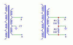
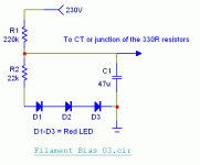
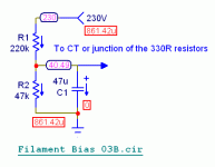
No navin you don't have to go with DC, though I've heard that some 6SN7's are nortorious for hum when operated on AC in low level circuits. I'm posting a couple of diagrams operating the filaments on AC. The two 330R resistors can be replaced with a 500R 1W wire-wound pot for hum balance. If you want, you can bias up your filaments using the second diagram. The red LED is there only for looks beacause I have a lot of them and gives a visual indication of operation. 20 to 40 volts bias should help with any hum as it reverse biases the cathode/filament. The 6SL7 has a max of +/- 90V h to k voltage, whereas the 6SN7:
Heater Positive with Respect to Cathode:
DC Component = 100V
Total DC and Peak = 200V
Heater Negative with Respect to Cathode:
Total DC and Peak = 200V
I use a free program called Front Panel Designer to help with the layout of a chassis. Though it was designed for front panels it can be used for the top, sides, bottom, whatever. I've printed them out and taped them to sheet metal or chassis and flipped on my drill press and... drill away!
 😉
😉 You can download it here:
www.frontpanelexpress.com/
Cheers
Wayne
Attachments
navin said:
I thought the heaters were AC? Do you mean to say the tubes have DC heaters. If so I would have to use another recitifier for the heater ckt right?
no, another option from what wayne posted would be to wind the 6.3volt heater winding biffiliar, so that the dc from wayne's circuit could be fed via the 6.3volt center tap. saves you 2 resistors or a humb balancing pot.
would love to see a schematic if you have one.
straight out of a 555 timer cookbook, with a tantalum caps, 22 and 4.7ufd in paralllel, series connected to a 1Meg timing resistor, your delay will be in excess of 30 seconds.
An externally hosted image should be here but it was not working when we last tested it.
cogsncogs said:...The two 330R resistors can be replaced with a 500R 1W wire-wound pot for hum balance.
If you want, you can bias up your filaments using the second diagram. The red LED is there only for looks beacause I have a lot of them and gives a visual indication of operation.
the transformer you showed has 4 primary windings and 3 secondary windings. Now I am confused. I thought what I needed was a 230V primary winding, and a 340-0-340, 6.3V, 12V and 70V secondary and we were trying to eliminate the need for a 12V seconrady by using the 6.3V instead.
I use a free program called Front Panel Designer to help with the layout of a chassis.
The 500 ohm Pot will make it bit more flexible. Thanks Wayne. Boy you turn out circuits so easily.
cogsncogs said:And here's the fil bias ckt.
I have to wait 60 seconds...
You designed this ckt faster than diyaudio's 60 sec wait! WOW! Now I AM IMPRESSED.
Tony said:
no, another option from what wayne posted would be to wind the 6.3volt heater winding biffiliar, so that the dc from wayne's circuit could be fed via the 6.3volt center tap. saves you 2 resistors or a humb balancing pot.
what is biffiliar? does it mean 6.3-0-6.3?
does it mean 6.3-0-6.3?
no, 3.15-0-3.15 volts, biffilliar means two wires are wound at the same time, these adds up to 6.3 volts.
Tony said:
no, 3.15-0-3.15 volts, biffilliar means two wires are wound at the same time, these adds up to 6.3 volts.
so this can be used for the heaters? remember this at 10A.
Originally posted by: Tony
no, 3.15-0-3.15 volts, biffilliar means two wires are wound at the same time, these adds up to 6.3 volts.
I think he means two wires at the same time, join them at opposite ends which would then be the center tap. Like this...
N or l\l with the slash being the CT...?
And yup 1, 10, or even 100A!
Cheers
Wayne
And I'm sort of re-posting the filament bias circuit this time showing voltage and current and no LED's and higher voltage = 40V.
Attachments
The header of a tube can be feed with AC or DC. It is a resistor that produce heat, and as with every kind of resistor, you get the same heating effect with the same amount of AC or DC voltage (at least with a low frequency AC as the main have).
In old TV set, the filament of the diode tube on the secondary of the high voltage alimentation is feed by the high voltage transformer at the line frequency: 16625 Hz in Europa. The same filament can be feed with DC without problem.
AC is commonly used because it is cheap, it need only 2 wires from the transformer to the tube. DC is better in audio because you don't get AC hum in the cathode circuit from the filament.
Another thing is the "polarisation" of the header in respect to the cathode. The manufacturer give a limit rating that must be respected. It can limit the voltage range of circuit as cascode or DC coupled amplifier, or at least made the filament circuit more complicated.
Another aspect of that filament polarisation is at you can use it in order to get less noise at the output, as always especially for the first stage of the amplifier.
In a tube, the near field of electrons near the cathode are not homogenous, and it is a souce of noise. The electrons have a negative charge and are attracted by the anode, but they will be attracted by the filament if the filament have a positive polarisation in respect to those electrons. It is a point where the elctrons will concentate near the cathode and where you will get les noise at the output.
This point can change between 2 tubes of the same model but different brands, so it is best to determine it by experimentation.
For power tube, it is enough to sut the light in the room completly down and observe the blue light inside the power tube. The filament polarisation will be correct when the blue light is concentrated, focused.
For the input stage, you must mesure the noise at the output of the amplifier with a voltmeter, without signal at the input and with the volume potentiometer at the maximum. The polarisation of the filament is correct when you get less noise.
It is no point to do that if the filament is AC powered, because you will get more hum from this AC as the noise from the electron field.
The same is right too for the middle point of the header. I saw some brands of ECC83 that give less noise when the middle point is at the middle and other brands that give less noise when it is no middle point, but when an extremity ic AC coupled to the ground with a resistor in parallel. So experimentation is the first rule here.
- Status
- Not open for further replies.
- Home
- Amplifiers
- Tubes / Valves
- EL34 schematic confusion