JojoD818 said:
As for point-to-point, I think that as close as possible is better so you minimize the signal's path.
The basic thing I remember is to follow the minimum distance between any two tubes so that the air through natural convection can cool down the tube naturally. With such a small distance, hook-up wires won't be necessary since caps and resistors have long leads.
minimise? I thought one should keep tubes atleast 3" apart to allow the air to circulate!
Now I am confused. I designed my prototype with a 4" c-c distance in mind between tubes.
also the 6SL7 in the circuit I have chosen has quite a few component attached to it and these will require some space.
navin said:
minimise? I thought one should keep tubes atleast 3" apart to allow the air to circulate!
Now I am confused. I designed my prototype with a 4" c-c distance in mind between tubes.
also the 6SL7 in the circuit I have chosen has quite a few component attached to it and these will require some space.
Several books adviced that power tubes be at least separated by a distance of 1-1/2 envelop width, some even states that it must be 2 envelop widths.
Let's say that your power tubes are about 1.5" in diameter, then your spacing from center to center must be at least 2-1/4". Of course this should be considered as your minimum and a longer distance between tubes has it's merits but chassis space is thereby sacrificed.
Heat is the enemy of electronics, it unncecessarily shortens a components life so your plan of a 4" c-c distance can be good.
However, it has been usual practice in tube building that the passive component's leads (caps, resistors, etc.) are used as hook-up wire since it's build type is point-to-point in nature.
The confusion is this: Have enough space/distance for your tubes to naturally cool but keep a short distance for your signal's path. Pretty confusing but I know you get the general idea.
JojoD818 said:
However, it has been usual practice in tube building that the passive component's leads (caps, resistors, etc.) are used as hook-up wire since it's build type is point-to-point in nature.
The confusion is this: Have enough space/distance for your tubes to naturally cool but keep a short distance for your signal's path. Pretty confusing but I know you get the general idea.
you also need to make enoug room for all teh passive components. I feel with my layout this can work as there are most passive componente betwen the 6SL7 and 6SN7 tubes and that is where this layout has most space.
one way would to configure the tube like a sun's rays. with a 6SL7 in the center, flancked by 2 6SN7 and the EL34 on teh sides
But after one adds the PS and OPTs to this layout oh lord what a mess one will have!
navin said:
you also need to make enoug room for all teh passive components. I feel with my layout this can work as there are most passive componente betwen the 6SL7 and 6SN7 tubes and that is where this layout has most space.
one way would to configure the tube like a sun's rays. with a 6SL7 in the center, flancked by 2 6SN7 and the EL34 on teh sides
But after one adds the PS and OPTs to this layout oh lord what a mess one will have!
that's why we diy. 😉
cogsncogs said:...I think you mean 2x .22uf (220nF)? Well you could but the ESR will get in the way of the purpose of this cap. This cap is placed as close as possible to bridge rectifier to help in the reduction of diode switching noise. 630V is non-negotionable! I'd recommend a tin & foil polypropylene, not a metalized cap if possible!
Not shown in the schematic is a 10nF, .01uF/2-3kV hi-voltage ceramic cap connected across the HV secondary. ..:
The power supply transformers finally arrived. They are big adn well made.
BTW Wayne, Hope your mom is doing better.
Also how big are these capacitors 100nf/630V and 10nf/2KV. I got a sample of each and the 100nf cap is barely 5mm dia and 30mm long while the snubber cap is about 12mm dia.
Reffering to the very first post in this thread:
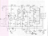
I once asked my self exactly the same question, and by coincidence run into a friend who in turn got advice from a legendary audio engineer in Sweden Mr. Lodstrom. The outcome is the attached schematic. I've built it, and it sounds very good considering the low price!
A few notes:
1) The high-side triodes pair have the catchode potential at 150V, hence they need a separate filament supply. Either you you wind a transformer with two 6.3V windings, or you just add a separate transformer for that filaments (6.3V/300mA).
2) The transformer should be Dynaco 470, i.e. transformers obtained from the relative cheap Dynaco ST-70, or replacement part for dito which is widely available.
3) Spend some time tweaking the FB chain, i.e. 47K/18K and the 47pF cap. Transformers vary in inductance/winding ratio, so theese values are only a starting point. Use a scope, but more important, your ears to get it right!
Hope you try it, and wont get dissapointed.
/Mike
Attachments
SwedishWings said:Reffering to the very first post in this thread:
I once asked my self exactly the same question, and by coincidence run into a friend who in turn got advice from a legendary audio engineer in Sweden Mr. Lodstrom. The outcome is the attached schematic. I've built it, and it sounds very good considering the low price!
A few notes:
1) The high-side triodes pair have the catchode potential at 150V, hence they need a separate filament supply. Either you you wind a transformer with two 6.3V windings, or you just add a separate transformer for that filaments (6.3V/300mA).
2) The transformer should be Dynaco 470, i.e. transformers obtained from the relative cheap Dynaco ST-70, or replacement part for dito which is widely available.
3) Spend some time tweaking the FB chain, i.e. 47K/18K and the 47pF cap. Transformers vary in inductance/winding ratio, so theese values are only a starting point. Use a scope, but more important, your ears to get it right!
Hope you try it, and wont get dissapointed.
/Mike
Hey thanks for the inputs.
I have managed to collect most of the active parts and build a chassis (stainless steel) see post 533 and 417 for the chassis.
My tubes are 6SL7 (1/2), 6SN7 (1), EL34 (2). My Power tranny and output trannys have also been got. some lovely genius called wayne did a lot of the work and with inputs from Jojo, raymoth, SY and all the other super patient guys I finally nailed a circuit..
the power supply is here
http://www.diyaudio.com/forums/attachment.php?s=&postid=823147&stamp=1137872257
My power tranny specs are on post 504. my output trannys were made in singapore and are U/L, pentode, and triode capable.
the main circuit is here
http://www.diyaudio.com/forums/attachment.php?s=&postid=811638&stamp=1136905599
the CCS is here
http://www.diyaudio.com/forums/showthread.php?s=&threadid=69042&perpage=10&pagenumber=22
unfortunately since december i have had one family emergency after another and have had no time to build this amp. Hope next year is better.
Life is just like that, time is to short for to everything - and it's so darn had to pick a hobby out of all the possible ones...
Anyway, just a thought:
your schematic implies a bias of 33mA / cathode (330mV/10ohm=33mA), which with 450V gives slightly below 15W total dispation. That's quite cold for HIFI stuff, and might not sound so good (you'll propably have some crossover distortion). Try to bias up the amp to around 22.5W dissiaption (that is 50mA/tube or 500mV over R22/R23).
Some may argue that the tubes last longer on a colder bias - but whats the point in building an expensive amp and not using it to it's potential?
A thing I usually did in the early years, was to put in a switch so I could switch between Pentode and Triode mode. Very easy and quite educational to hear the difference.
Another educational thing you might wanna try is to disconnect either side of C3 and try to run the amp in SE (single ended) mode, You'll only have a couple of watts output when operating in SE mode, and you'll have a lot more even harmonics (the normal PP coupling eliminates theese effectively, but they can bee sweet). However, do not try to rip out one tube, as they are both needed to keep the DC current balanced in the transformer. This means that you basicly can have three different amps in one!
I really hope you got to finninsh this project. My first was almost a religous experience 🙂 those were the days, now I'm getting freakin ol'...
Good luck and good bless!
I have not followed this regularly, so must not be too wise!
But two remarks:
One does not need two heater windings for the circuit given by SwedishWings (#567). If you tie the heater winding to somewhere about 70V - 80V positive, no heater-cathode voltages would be exceeded.
Then I notice a general idea that signal path must be kept short. This is not important in audio! Just about all wiring that would be contained inside any normal power amplifer chassis is very short with respect to what would matter in audio. Folks seem to think only about "live" signal paths, but one must remember that power supply leads are as much in the (return) signal path as coupling capacitor leads, and these are sometimes long - signal current flows in a circuit (circle).
The important point is to keep "live" signal leads away from possible sources of hum, feedback, etc. This is more likely in the case of long leads, but not necessarily so if one keeps one's eyes open.
Regards.
SwedishWings said:Reffering to the very first post in this thread:
I once asked my self exactly the same question, and by coincidence run into a friend who in turn got advice from a legendary audio engineer in Sweden Mr. Lodstrom. The outcome is the attached schematic. I've built it, and it sounds very good considering the low price!
A few notes:
1) The high-side triodes pair have the catchode potential at 150V, hence they need a separate filament supply. Either you you wind a transformer with two 6.3V windings, or you just add a separate transformer for that filaments (6.3V/300mA).
2) The transformer should be Dynaco 470, i.e. transformers obtained from the relative cheap Dynaco ST-70, or replacement part for dito which is widely available.
3) Spend some time tweaking the FB chain, i.e. 47K/18K and the 47pF cap. Transformers vary in inductance/winding ratio, so theese values are only a starting point. Use a scope, but more important, your ears to get it right!
Hope you try it, and wont get dissapointed.
/Mike
hey, nice circuit you got there, this is the first time is see SRPP drivers. maybe you might want to try long-tail pair phase splitters for you input stage.
Perhaps the SRPP stage needs an explanation for uninitiated: the SRPP coupling replaces the plate load with a current source wich gives 1) hi gain, 2) low output impedance, 3) and lower distortion.
I'm not sure why this coupling is not used more often, after all, it does have a lot of benefits, in particular when it comes to driving output tubes. Any comments?
I'm not sure why this coupling is not used more often, after all, it does have a lot of benefits, in particular when it comes to driving output tubes. Any comments?
Just did some math on the SPRR circuit above:
Gain: 33dB
Zout: 28K (!)
F_low (-3dB): 5.3Hz (with 270K load)
F_high (-3dB): > 1MHz (with 270K load)
Note the combination of bandwith and Zout!
/Mike
Gain: 33dB
Zout: 28K (!)
F_low (-3dB): 5.3Hz (with 270K load)
F_high (-3dB): > 1MHz (with 270K load)
Note the combination of bandwith and Zout!
/Mike
SwedishWings said:Perhaps the SRPP stage needs an explanation for uninitiated: the SRPP coupling replaces the plate load with a current source wich gives 1) hi gain, 2) low output impedance, 3) and lower distortion.
I'm not sure why this coupling is not used more often, after all, it does have a lot of benefits, in particular when it comes to driving output tubes. Any comments?
The problem of the SRPP is at the output can be balanced for only 1 load impedance. See Tube CAD: SRPP
Dominique_free said:
The problem of the SRPP is at the output can be balanced for only 1 load impedance. See Tube CAD: SRPP
I do not believe that is applicable in this circuit. To the best of my knowledge, the consideration in the Tube CAD article is to drive low impedance load, where the output impedance of the SRPP stage is close to the load impedance.
In the circuit i posted the load impedance is around 250K, and the need for balancing is not really relevant given the impedance ratio of almost 1:10 (i.e. 28K output impedance vs 250K load impedance). But then again, maybe i'm totally wrong 🙂
Let me firstly say that the 19 odd pages of the quoted "Tube CAD: SRPP" is excellent reading for those not fully conversant with the characteristics of the SRPP (interesting story about the aluminium and the cat - how true!).
But SwedishWings is (are?) right regarding balanced operation into high load impedances. Still, the optimal use of this circuit is where some load current is required. On p.4 of the quoted article it is suggested that for use as a pure voltage amplifying stage (large load) this configuration is not optimal (also p.5, last paragraph).
But this does not take into account requirements for large voltage swings. The alternatively suggested common cathode stage will begin to fall short, the higher the amplitude (unless Gm loaded). So will the SRPP at the bottom end, as the anode of the first triode has a Vmin. limit, which will be quite high for an ECC83). Calculation with the given formulae will yield some results but not linearity for high voltage drives - unless one can run a simulation. [Beware of some confusion between RL (as Rl) and R1 in the formulae].
Still, a most interesting topic. Is someone able to simulate this as a power stage driver and broaden our horizons?
Regards.
Johan Potgieter> Yes, i think you are right in many aspects, and I do agree that the circuit is not the ulimate, but then, what is the ulimate solution? The common solution with an anode resistor? I've tried both circuits in the same amp and experienced a hughe sonic improvement with the proposed currcuit. Why?
Maybe part of the explanation is
1) The extreme bandwith is hard to achive in other ways, and will allow for better error correction in the feedback chain, hence the net distortion product of the amplifier will propably be better than the common anode resistor solution that lacks bandwith and will introduce more phase errors.
2) Transient response will be better, again thanks to the extreme bandwith for error correction.
Try it! We can argue infinitum about the theory, but the ultimate judge will be our ears. I did, I liked what I hear, and it's one of my favorite amps today (actually, I got a few with different transformers and power tubes). It has midrange clarity and a very clean brilliant top that few other I've heard can offer. I really hope someone else pick up this ideas, and try to refine the concept!
--- I'm human, and live to learn, so if I'm wrong, spank me

Cheers!
Maybe part of the explanation is
1) The extreme bandwith is hard to achive in other ways, and will allow for better error correction in the feedback chain, hence the net distortion product of the amplifier will propably be better than the common anode resistor solution that lacks bandwith and will introduce more phase errors.
2) Transient response will be better, again thanks to the extreme bandwith for error correction.
Try it! We can argue infinitum about the theory, but the ultimate judge will be our ears. I did, I liked what I hear, and it's one of my favorite amps today (actually, I got a few with different transformers and power tubes). It has midrange clarity and a very clean brilliant top that few other I've heard can offer. I really hope someone else pick up this ideas, and try to refine the concept!
--- I'm human, and live to learn, so if I'm wrong, spank me
Cheers!
No, S-W, no spanking (you are problay younger than I am and can run faster).
I may not have been totally clear. I did say that the common cathode stage (i.e. with just an anode resistor) is also not optimal. I was merely commenting on the contents of that article. That is why I also hoped that someone can analise this on Spice or something. I meant that if this is not ideal, so is nothing else, and shortcomings might well be a little academic (we researchers sometimes fall for that temptation!).
I fully agree with the superior frequency response/transient response. In fact, in what I humbly believe to be a good transistor amplifier, I use this configuration as a driver instead of the usual VAS circuit, with measured superiority. (Oh come on now guys, don't cringe at the word "transistor", all your PCs work with them!).
I also respect your experience. When I get back home, I will certainly construct this circuit and do some measurements. (Sadly listening tests with me old ears are no longer normative, them going only to some 7-8 KHz and all that. )
)
Regards.
I may not have been totally clear. I did say that the common cathode stage (i.e. with just an anode resistor) is also not optimal. I was merely commenting on the contents of that article. That is why I also hoped that someone can analise this on Spice or something. I meant that if this is not ideal, so is nothing else, and shortcomings might well be a little academic (we researchers sometimes fall for that temptation!).
I fully agree with the superior frequency response/transient response. In fact, in what I humbly believe to be a good transistor amplifier, I use this configuration as a driver instead of the usual VAS circuit, with measured superiority. (Oh come on now guys, don't cringe at the word "transistor", all your PCs work with them!).
I also respect your experience. When I get back home, I will certainly construct this circuit and do some measurements. (Sadly listening tests with me old ears are no longer normative, them going only to some 7-8 KHz and all that.
)Regards.
- Status
- Not open for further replies.
- Home
- Amplifiers
- Tubes / Valves
- EL34 schematic confusion