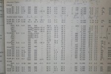
Load impedances for EL34 become very confusing with changes in topology, biasing methods, operating point and class of operation - just look at this table of possible EL34 applications from Duncan Amps!. For some reason, the Duncan Amps table shows Vg2 being higher than Va in many instances, which I think is a misprint.
Mullard didn't give any recommendation on the optimum load for EL34 UL PP with fixed bias, and neither did any other manufacturer to my knowledge. The only data sheets I've seen for UL are about cathode bias (usually 6.6k P-P). I've seen the odd mention of lower impedances with fixed bias from other sources, like 4.5k P-P, but nothing that was very authoritative or clear. Claus Byrith, in his adaptation of the Mullard 5-20 from cathode bias to fixed bias, ignored the issue. He did use a lower load impedance but only because he had to choose a transformer from Lundahl.
Mullard didn't give any recommendation on the optimum load for EL34 UL PP with fixed bias, and neither did any other manufacturer to my knowledge. The only data sheets I've seen for UL are about cathode bias (usually 6.6k P-P). I've seen the odd mention of lower impedances with fixed bias from other sources, like 4.5k P-P, but nothing that was very authoritative or clear. Claus Byrith, in his adaptation of the Mullard 5-20 from cathode bias to fixed bias, ignored the issue. He did use a lower load impedance but only because he had to choose a transformer from Lundahl.
I very rapidly checked my previous entry! ... Not quite 😱 but I may have given the wrong impression. I did in fact not get the idea of a preferred operation from the Mullard EL34 data sheets themselves but from a publication or two. I think the original 520 design article (by a Mullard designer) gave that idea for low (lowest?) distortion, but don't have it at hand now. But yes, there is not a single optimum point - as there is not for other tubes.
[As an aside, sometimes expression of distortion as a % instead of a signal level can also be misleading (not specifically EL34). Percentage is of the maximum output, not signal voltage. Comparing triode and pentode operation, UL might show a higher % but actually be lower than for triode, while also still having some more headroom, while triode runs out of steam. Just an observation.]
[As an aside, sometimes expression of distortion as a % instead of a signal level can also be misleading (not specifically EL34). Percentage is of the maximum output, not signal voltage. Comparing triode and pentode operation, UL might show a higher % but actually be lower than for triode, while also still having some more headroom, while triode runs out of steam. Just an observation.]
Johan Potgieter said:...Percentage is of the maximum output, not signal voltage. Comparing triode and pentode operation, UL might show a higher % but actually be lower than for triode, while also still having some more headroom, while triode runs out of steam. Just an observation..
this is exactly what I was thinking. In the end it really matters how much power your speaker needs. If you (and your speakers) can make do with about 6-8W then triode is an obvious choice, if however you (and your speakers) "need" 15W or so then A-B UL would make most sense. If you need more than 20W it would make more sense to consider another tube (6550, KT88, etc..) instead of pushing the EL34 to their limits.
Any device when pushed to it's limits will not perform well for very long.
ray_moth said:Load impedances for EL34 become very confusing with changes in topology, biasing methods, operating point and class of operation - just look at this table of possible EL34 applications from Duncan Amps!. For some reason, the Duncan Amps table shows Vg2 being higher than Va in many instances, which I think is a misprint.
For me it is quite confusing since there seems that 3rd and 4th push more current than the valve rating and have different power at the although everything is the same... Others just show the confusion I had and why I asked the question I did...
Pred
Johan Potgieter said:I think the original 520 design article (by a Mullard designer) gave that idea for low (lowest?) distortion, but don't have it at hand now.
The 20W Mullard amp with Partridge o/p tranny shows 0.05% thd at 400Hz; Pout =20W. IM thd= 0.7% 40c/s-10Khz 4:1 amplit ratio. Va= 400V+.
Vin =220mV; 30dB global nfb.
richj
Something else I've often wondered: why are the given bias voltages so low.
The datasheets for Class A SE are around -12 or -14, which I understand well enough, but for A/B PP (UL) they often give something between about -35V to -40V.
All the EL34 datasheets I've come across [incl. Mullard] have pentode curves which go as low as -25V, sometimes -30V. For A/B where you want a liiiitttle bit of overlap, something like -25V or -28V seems more reasonable?
Is this a result of the U/L connection pulling the curves "up" the graph or something? :s
Or are they referring to A/B in triode mode (in which case the datasheets go down to around -35, and from looking at the Mullard, -40V could fit on too)
Ta
If you look at the recommended plate voltage and current in each case, you'll see why that is.The datasheets for Class A SE are around -12 or -14, which I understand well enough, but for A/B PP (UL) they often give something between about -35V to -40V.
SE has to be Class A, which needs an operating point with low plate voltage with high quiescent plate current. That means low bias voltage.
Class AB can use a much higher plate voltage, because its quiescent current is low. That requires a higher bias voltage.
Also PeteN,
From another viewpoint: One uses as high a bias (low Ia.quiescent) as possible to limit average anode dissipation. But obviously if the bias is too high one approaches class B with obvious disadvantages. Thus one settles for a bias just far enough away from class B, where harmonic distortion (predominantly cross-over) sinks away into the noise floor, as it were. There is generally a bias point where the gm reduction of the "out-going" tube is well complemented by the increasing gm of the "incoming" tube (which is coming out of zero Ia).
Now this is an over-simplified explanation of optimal class AB operation, but I am trying to give an understandable picture.
Johan Potgieter said:Also PeteN,
From another viewpoint: One uses as high a bias (low Ia.quiescent) as possible to limit average anode dissipation. But obviously if the bias is too high one approaches class B with obvious disadvantages. .
Now this is an over-simplified explanation of optimal class AB operation, but I am trying to give an understandable picture.
Ah! over-simplification is impossible.
In the real world all this is a bit different. One cannot ignore the o/p tranny from the picture and the annoying problem varies with each o/p tranny maker. Anyone with a thd analyser will tell you that an AB amp powered into a dummy load at 10Khz instead of 1Khz will notice the thd rockets perhaps x10 compared to 1Khz even with global feedack. The o/p tranny parasitics and bandwidth come into play also the LS isn’t part of the load. As mentioned, the decrease of quiescent current (to reduce anode dissipation) creates a bentish plate curve towards cutoff B. So in every case even at modest power levels I tried there is a collelation between thd and quiescent current. No plate line is linear so operating an AB p-p stage near to class A i.e no load to full load current with 5% difference will give best results at both frequencies. The higher quiescent current tries to make an oblong transformer BH curve straighter around zero by better plate damping..as class A operates over the full part of the cycle.
I find replacing tubes with larger anode areas for UL operation is recommended. So that implies for a given power the best way to run EL34‘s and other power tubes is in parallel pairs with lower B+. Of course they would last longer.
When on examines amp designs from yesteryear one will find a tendency to use high quiescent currents and not uncommon to set up with cherry red plates. So much for the" green footprint".
richj
Och!
So much for a well-meant endeavour in the middle of the night to bring home basics ... Yes, the transformer. I cannot disagree with that - quite some time since I had a working spectrum analyser, and "distance lends enchantment to the view".
I am somewhat surprised with your experience of having to come so close to class A for satisfactory results, also data sheets indicate less severe distortion. Perhaps I have been fortunate with my OPTs.
But, bottom line; I cannot disagree with Rich ... high time I get that spectrum analyser facility back into shape (better sound-card etc.) and unfizzle the old grey matter.
Thanks Rich!
(and with our present temperatures "down" here, wish I could be with you high in the Alps!)
So much for a well-meant endeavour in the middle of the night to bring home basics ...
Yes, the transformer. I cannot disagree with that - quite some time since I had a working spectrum analyser, and "distance lends enchantment to the view".I am somewhat surprised with your experience of having to come so close to class A for satisfactory results, also data sheets indicate less severe distortion. Perhaps I have been fortunate with my OPTs.
But, bottom line; I cannot disagree with Rich ... high time I get that spectrum analyser facility back into shape (better sound-card etc.) and unfizzle the old grey matter.
Thanks Rich!
(and with our present temperatures "down" here, wish I could be with you high in the Alps!)
Johan Potgieter said:Och!
high time I get that spectrum analyser facility back into shape (better sound-card etc.) and unfizzle the old grey matter.
I bought an ADC216 a few years ago, and it's good value for the money. The software is pretty good and does a resonable job as both scope and spectrum analyzer. The only bad thing about is that it uses the LPT port.
I was fortunate enough to get the 16 bit verision (ADC216), but it i think it's not in production anymore. The ADC212 has only 80dB dynamic range, but otherwise the same as the ADC216.
http://www.picotech.com/212_6.html
Cheers!
I find replacing tubes with larger anode areas for UL operation is recommended. So that implies for a given power the best way to run EL34‘s and other power tubes is in parallel pairs with lower B+. Of course they would last longer.
So much for the" green footprint".
You mean Parallel Push-Pull? Wont that change the iron used as well? Also does that not mean that one has to keep 4 or more tubes biased equally?
You mean Parallel Push-Pull? Wont that change the iron used as well? Also does that not mean that one has to keep 4 or more tubes biased equally?
Hey Navin, what happend to your project?
Hey Navin, what happend to your project?
It has been delayed indefinitely becuase of some personal issues. I do hope to coplete it someday. I got most of the parts (a few odds and ends like the 630V filter capcacitors) are missing.
Sorry to hear that - hope you will be able to startup again soon.It has been delayed indefinitely becuase of some personal issues. I do hope to coplete it someday. I got most of the parts (a few odds and ends like the 630V filter capcacitors) are missing.
- Status
- Not open for further replies.
- Home
- Amplifiers
- Tubes / Valves
- EL34 schematic confusion