Hello,
A few time ago I made a 40w Push-Pull amplifier with EL34 tubes, based on this description by Claus Byrith. : EL34 Push-Pull
The sound is nice, no any hum on 91db speakers. Last week I did some measurments:
Square wave at 100hz/1khz/10khz:


The frequency respponse is also good: the -3db is at 4Hz and 50kHz.

But what I don't really like is the spectrum:

As you see the distorsion factor is good but the spikes around 1khz base frequency at 700, 800, 900, 1100, 1200,1300 hz is prety high. Is about -60dB the highest.
After some research I found the problem is comming from the power supply which has about 7V pp 100Hz ripple at B+ for EL34 plate+G2. For the phase inverter and input tube the ripple is almost 0,
If I tried to change the filter capacitors from 220uF to 470uF the ripple became aprox. 3.5V pp and the spikes on spectrum lovered to -67db. Still visible.

Any comment about this? Is it acceptable or need more filter on power supply? Unfortunatelly I have no place for a choke because the design is ready.
Have a nice day!
A few time ago I made a 40w Push-Pull amplifier with EL34 tubes, based on this description by Claus Byrith. : EL34 Push-Pull
The sound is nice, no any hum on 91db speakers. Last week I did some measurments:
Square wave at 100hz/1khz/10khz:
The frequency respponse is also good: the -3db is at 4Hz and 50kHz.
But what I don't really like is the spectrum:
As you see the distorsion factor is good but the spikes around 1khz base frequency at 700, 800, 900, 1100, 1200,1300 hz is prety high. Is about -60dB the highest.
After some research I found the problem is comming from the power supply which has about 7V pp 100Hz ripple at B+ for EL34 plate+G2. For the phase inverter and input tube the ripple is almost 0,
If I tried to change the filter capacitors from 220uF to 470uF the ripple became aprox. 3.5V pp and the spikes on spectrum lovered to -67db. Still visible.
Any comment about this? Is it acceptable or need more filter on power supply? Unfortunatelly I have no place for a choke because the design is ready.
Have a nice day!
Attachments
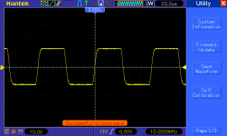

I would say your EL34 PP amp performs very well. There's no ringing even at 10KHz. Good job.
Wondering which output transformer are you using?
Johnny
Wondering which output transformer are you using?
Johnny
If the sound is good and you are just looking at the scope, I would say don't fix what isn't broken. As kmtang says, the square wave performance is very, very good. If I'm reading the captures correctly, it looks like you actually increased harmonic distortion by increasing the capacitance. Am I wrong?
Yes, don't fix what is not broken...
My amplifiers have more noise floor of the power supply , however the waterfall of harmonics only appears on mine when the amplifier gets into the clipping , when thd is more than 1% .
on a pp you should get a low 2n because of the cancelation in the output when valves are balanced, and higher 3rd, and no other significant thd other than the 120 hz or 60hz PS noise.
I just found out one of my ssd drive it out of service ... but anyway, at what power is the waveform, if it is at like 15 watts, this could just be normal.
Hi
If you see ripple on a clipped output it means the supply needs better filtering.
I believe what the spectrum is showing is intermodulation caused by poor grounding and wire layout. This is pretty common in hand-wired builds, and even with PCBs that are not laid out correctly. IM products are more than just the sum and difference of the test signal and the "100Hz" ripple; there will be frequencies all up and down the spectrum that seem entirely unrelated. Also note that the ripple is not a sine ave unto itself, and is comprised of many more frequencies overlayed to achieve the saw-tooth shape.
Overall, the THD is good as tube amps go. IM is nasty at even small levels.
Hi Istvan58,
Great results, well done.
Try different chokes... and put 220uF back. Let us know how it sounds and show us the harmonics/distortion spectre...
Great results, well done.
Try different chokes... and put 220uF back. Let us know how it sounds and show us the harmonics/distortion spectre...
Unfortunatelly is a finished compact design. No place to add choke . But as a trial I will do it too see what happens.
My feeling the 100Hz interemodulation with the 1Khz base signal is comming due to modulation on the EL34 G2. Is an ultraliniar design and the 100Hz ripple is about 7Vpp, with extra caps ia about 3.5Vpp. If will have some time I will try it with an external supply with low ripple.
The layout I think is good, is on PCB. The 100Hz hum is at -95....-100dB. Is totally quiet on speaker. Only with signal I see the intermodulation with 1kHz base freq. But I think this level beeing below -60dB not as bed. I wondering how other tubeamp performs.
Last edited:
Hello, Is an SU 60 b core from Waasner Germany. ( Link ) Is 33% tap for UL. The windings aragement is a tricky. After about 20....25 trials I got the final version. No oscilating even with no load. The frequency response is also good. Is not easy to buy core from Waasner. I bought some 5 years ago. Now the price is increased about 4 times. An not selling only for companies. But I think is others on the market with same cores.
I agree that G2 ripple is canceled in PP output stage. I don't see any with no signal. It looks like just modulating the signal when applied. But as I told is at about -65dB mybe I can't worried about it.
Instead of a choke you could consider a capacitor multiplier, using a MOSFET. This could bring the ripple down quite a bit. This doesn’t requite much space; the MOSFET could be cooled by the chassis using proper insulation (mica or equivalent).
Regards, Gerrit
Note: the link in post 14 seems to be dead (at least for now).
Regards, Gerrit
Note: the link in post 14 seems to be dead (at least for now).
Yes, I have a capacitor from B+ to ground too. Make sure the MOSFET can handle the current to load this extra capacitor. And of course it has be OK for the B+ voltage as well. I don’t see any Z4 in your diagram, but a single zener will do. A SPP04N80C3 could be OK, just check the SOA values for DC with regards to your power supply needs.
Regards, Gerrit
Note: the link is working now!
Regards, Gerrit
Note: the link is working now!
- Home
- Amplifiers
- Tubes / Valves
- EL34 push-pull